



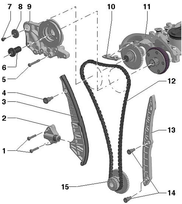
28.1. Timing chain installation details 1, 5. Bolt, 9 Nm; 2. Chain tensioner 12; 3. Chain tension bar 12; 4, 14. Guide pins, 20 Nm; 6. Timing phase adjustment valve, left-hand thread, 35 Nm; 7. Bolt, subject to replacement, 8 Nm, then tighten to an angle of 90°; 8. Washer; 9. Bearing holder; 10, 13. Chain guide bar; 11. Camshaft housing; 12. Timing chain; 15. Crankshaft sprocket, when installed, the protruding edges of the two teeth on the end of the sprocket must be aligned with the beveled edges of the two teeth on the end of the crankshaft
2. Remove the upper timing chain cover (see Section 27).
3. Unscrew the timing phase control valve using the T10352/1 tool (see illustration).
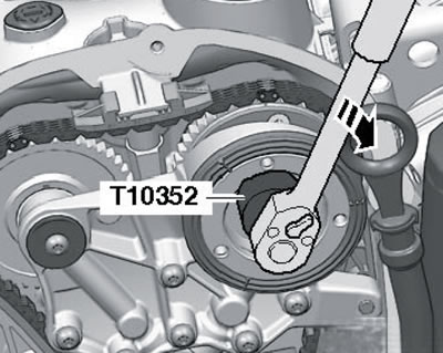
28.3. Unscrewing the timing phase control valve
Note: The valve has a left-hand thread.
4. Remove the bolts (see illustration) and remove the bearing holder.
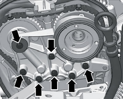
28.4. Bearing holder fastening
5. Using the T10355 key, turn the crankshaft clockwise to the position corresponding to the TDC of piston No. 1. In this case, the notch on the pulley should be opposite the mark on the lower timing chain cover (arrow on the illustration), and the marks (1) on the camshaft sprockets must face upwards. If the marks on the shafts are not facing up, turn the crankshaft one more revolution.
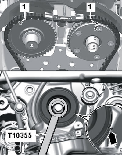
28.5. Position of TDC of piston No. 1
6. Remove the lower timing chain cover (see section 27).
7. Press the oil pump drive chain tensioner in the direction of the arrow (see illustration) and secure the tensioner in this position with pin T40011. Remove the tensioner (1) and the oil pump drive chain from the crankshaft sprocket.
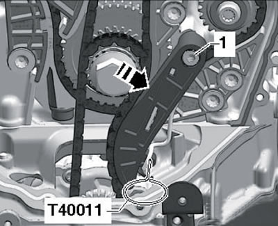
28.7. Removing the oil pump chain
8. Together with an assistant, using a Phillips screwdriver with a diameter of approximately 2 mm, lift the timing chain tensioner locking element in the direction of the arrow (1 in the illustration), press the tension bar in the direction of the arrow (2) and secure the tensioner with the T40011 locking pin.
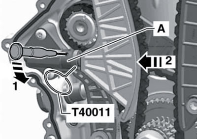
28.8. Timing chain weakening
Note: Do not bend or pry the lock washer (A). If the automatic tensioner reset does not work, the chain may jump off the tooth during a cold start and cause engine damage.
9. Remove the tension bar (2 in the illustration) and the timing chain guide plate (1), and then remove the timing chain. This will move the intake camshaft clockwise.
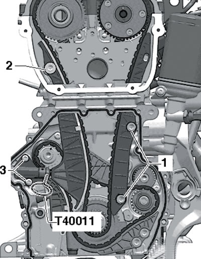
28.9. Removing the timing chain tensioner bar
10. Place the timing chain on the sprockets of the exhaust camshaft and crankshaft so that its colored links are located opposite the marks on the sprockets (see illustration). Have an assistant turn the intake camshaft with an open-end wrench in the direction of the arrow and hold it in this position until the timing chain tensioner and guide rails are installed. Place the timing chain on the intake camshaft sprocket so that the mark on the chain is opposite the colored chain link. Install the timing chain guide rail and tighten the bolts (1 in illustration 28.9), then install the tension bar and tighten the bolt (2). Now the key can be removed from the intake camshaft.
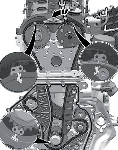
28.10. Marks on the timing chain and sprockets
11. Install the bearing holder and tighten its mounting bolts by hand (see illustration 28.4). Remove the T40011 locking pin from the timing chain tensioner and tighten the bearing holder mounting bolts to 9 Nm.
12. Tighten the timing phase check valve (with left-hand thread).
13. Install the remaining parts in the reverse order of removal.