



Contents: Oil separator coarse filter ⬇ Oil pan (lower part) ⬇ Oil pump ⬇ Oil pan (upper part) ⬇ Oil cooler ⬇
1. The installation details of the lubrication system components are shown in the illustrations.
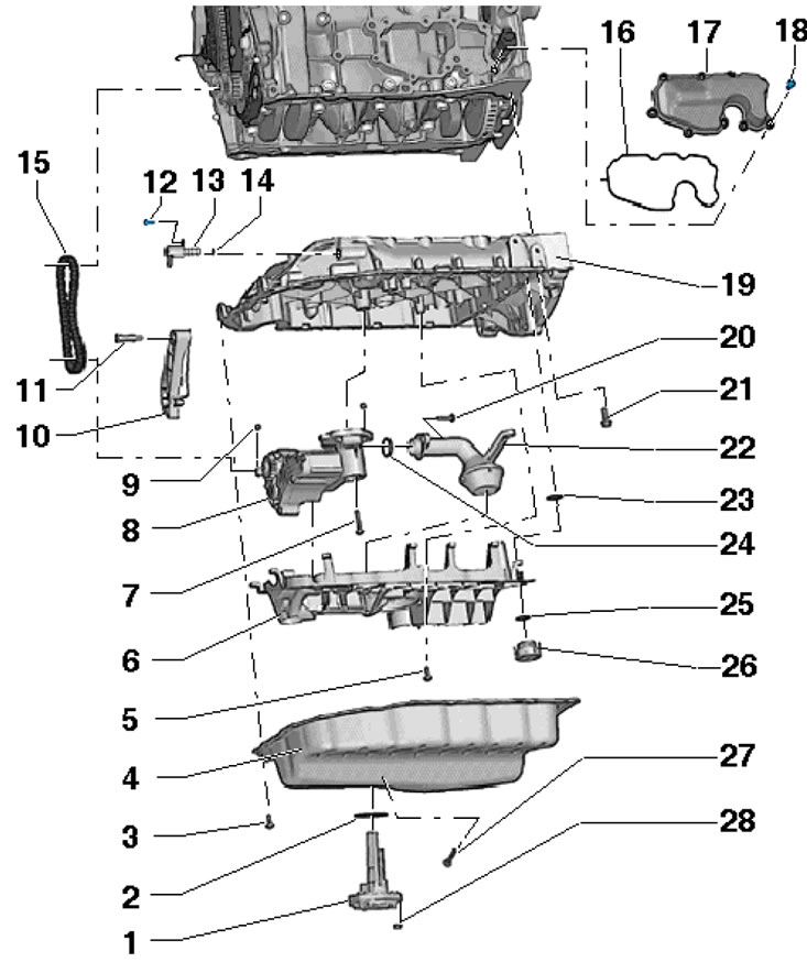
32.1a. Oil pan and oil pump installation details 1. Sensor "G266" of engine oil level and temperature; 2. Sealing ring, subject to replacement; 3. Bolt, subject to replacement, 8 Nm, then tighten to an angle of 45°; 4. Lower part of the oil pan; 5. Bolt, 9 Nm; 6. The soothing plate is subject to replacement; 7. Oil pan mounting bolts, 9 Nm; 8. Oil pump; 9. Centering sleeve; 10. Chain tensioner; 11, 12. Bolt, 9 Nm; 13. Valve "N428" for regulating engine oil pressure; 14. Sealing ring, subject to replacement; 15. Oil pump drive chain, mark the direction of movement before removing; 16. Gasket, subject to replacement; 17. Oil separator coarse filter; 18, 20. Bolt, 9 Nm; 19. Upper part of the oil pan; 21. Bolt, subject to replacement, 15 Nm, then tighten to an angle of 90°; 22. Suction tube; 23-25. Sealing ring, subject to replacement; 26. Return flow control tube (non-return valve); 27. Drain plug, subject to replacement, 30 Nm; 28. Bolt, 9 Nm
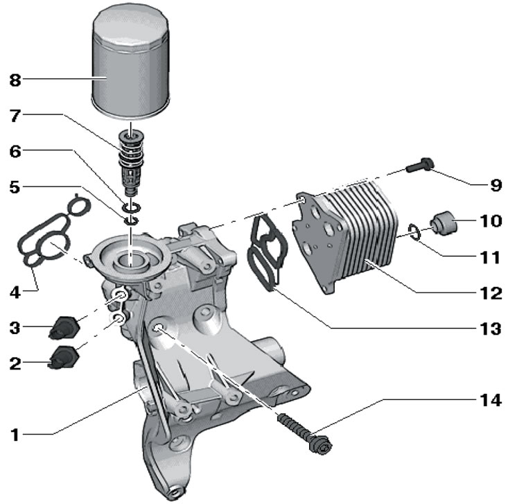
32.1b. Installation details of the oil filter, oil cooler and sensor "F1": 1. Auxiliary bracket, with built-in oil filter holder; 2. D/V "F22" high pressure engine oil, blue, 2.15 + 2.95 bar, 20 Nm; 3. D/V "F378" low pressure engine oil, brown, 0.55 + 0.85 bar, 20 Nm; 4, 13. Gasket, subject to replacement; 5, 6. Sealing ring, subject to replacement, is an integral part of module 7; 7. Valve module; 8. Oil filter, 22 Nm; 9. Bolt, 15 Nm; 10. Connection; 11. Sealing ring, subject to replacement; 12. Oil cooler; 14. Bolt, subject to replacement, 20 Nm, then tighten to an angle of 90°
Oil separator coarse filter
2. Remove the sound insulation under the engine compartment (see Chapter 11).
3. Remove the bolts (1-9 in the illustration), remove the coarse oil separator filter and plug the exposed holes to prevent dirt from entering the lubrication system.
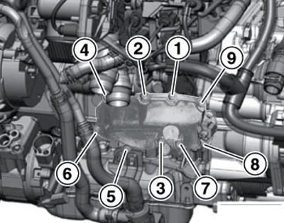
32.3. Coarse filter mounting bolts
4. Replace the gasket and install the coarse filter. Tighten the filter mounting bolts in the following sequence: (1-9 in Illustration 32.3) with a force of 9 Nm.
Oil pan (lower part)
5. Remove the sound insulation under the engine compartment (see Chapter 11).
6. Drain the engine oil (see Section 6 Chapter 1).
7. Disconnect the connector of the "G266" oil temperature and level sensor on the bottom of the pan.
8. Remove the bolts (1-20 in the illustration) and remove the lower part of the oil pan. If necessary, lightly tap the tray with a rubber-faced hammer.
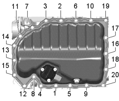
32.8. Sequence of unscrewing and tightening the bolts securing the lower part of the oil pan
9. Remove any remaining sealing material from the mating surfaces of the lower and upper parts of the oil pan and clean them from oil and grease. It is recommended to use a chemical remover to remove sealant and grease.
10. Apply a bead of silicone sealant D 174 003 A2 with a diameter of 2-3 mm to the mating surface of the lower part of the oil pan (see illustration) and within 5 minutes after that, install the oil pan.
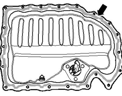
32.10. Sealant application scheme
Note: The sealant layer should not be too thick, otherwise excess sealant will be squeezed out and may lead to clogging of the oil channels. Tighten the new pan mounting bolts in sequence (1-20 in illustration 32.8) in several approaches: first by hand. then with a force of 8 Nm, and then pull them to an angle of 45°.
11. Further installation is carried out in reverse order. Allow the sealant to dry for at least 30 minutes before adding oil.
Oil pump
12. Remove the lower part of the oil pan (see subsection above).
13. Remove the bolts (see illustration) and remove the sedative plate. Invite an assistant.
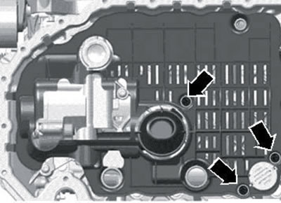
32.13. Fastening of the damping plate
14. Remove the bolts (see illustration 33.14a), pull the chain tensioner back with the T10118 tool (see illustration 33.14b) and ask an assistant to remove the pump.
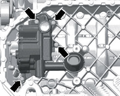
32.14a. Oil pump fasteners
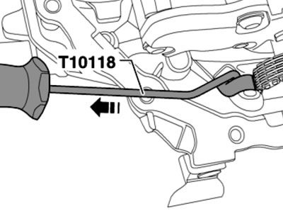
32.14b. Removing the oil pump
15. Before installing the oil pump, make sure that the suction pipe mesh and oil galleries in the upper part of the oil pan are clear. Make sure both centering bushings are installed.
16. Pull the chain tensioner back with the T10118 tool (see illustration 32.14b) and install the pump, placing the chain on its sprocket.
17. Further installation is carried out in reverse order. Use a new pacifier plate. because when tightening its fasteners, the plastic ribs that ensure a play-free fit break.
Oil pan (upper part)
18. Remove the sealing flange with the rear crankshaft oil seal (see Section 26).
19. Remove the oil pump (see subsection above).
20. Remove the right front wheel arch liner (see Chapter 11).
21. On models with additional heating, loosen the clamp (1 in illustration 15.12), unscrew the bolt (2) and remove the additional heater muffler.
22. Remove the bolts (arrows in illustration 25.4) and remove the air pressure tube by lifting the clamps (1 and 2). Loosen the air pressure tube and wiring bracket fasteners on the top of the oil pan.
23. Disconnect the connector (1 in the illustration) "N428" fuel pressure adjustment valve (3).
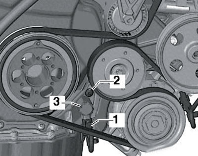
32.23. Valve connector "N428"
24. Remove the bolts (14 and 15 in illustration 27.10) lower timing chain cover.
25. Remove the bolts (1-14 in the illustration) and remove the upper part of the oil pan. If necessary, tap it lightly with a rubber-faced hammer.
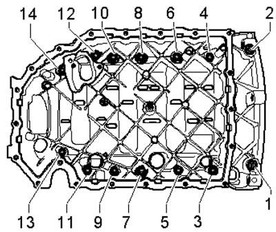
32.25. Sequence of unscrewing and tightening the bolts securing the upper part of the oil pan
Note: When removing the upper oil pan, the oil pump chain tensioner spring will pop out of the oil pan and into the lower timing chain cover, so do not grasp the area between the upper oil pan and the lower timing chain cover. Pry the oil pan on the transmission side first and do not damage the timing chain cover.
26. Remove any remaining sealing material from the mating surfaces of the upper part of the oil pan, cylinder block and lower timing chain cover. Clean them from oil and grease. It is recommended to use a chemical remover to remove sealant and grease. Make sure that the oil galleries in the upper part of the oil pan and in the cylinder block are clear.
27. Make a fixture by bending a welding electrode with a diameter of 1.8-2.0 mm as shown in the illustration. Dimension (a) should be approximately 10 mm. Pull the tensioner spring in the direction of the arrow using the T10118 tool and fix the spring by inserting the tool you made into the hole in the tensioner.
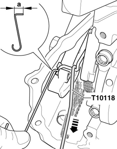
32.27. Retracting the oil pump chain tensioner spring
28. Apply a bead of silicone sealant D 174 003 A2 with a diameter of 2-3 mm to the mating surface of the upper part of the oil pan (see illustration) and within 5 minutes after that, install the oil pan flush with the cylinder block on the transmission side.
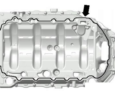
32.28. Sealant application diagram
Note: The sealant layer should not be too thick, otherwise excess sealant will be squeezed out and may lead to clogging of the oil channels. Tighten the new pan mounting bolts in sequence (1-20 in illustration 32.25) with a force of 15 Nm, and then pull them to an angle of 90°.
29. Tighten the new lower timing chain cover lower bolts to 8 Nm, then tighten them to a 45° angle.
30. Using a screwdriver, pull the bent electrode out of the tensioner - the spring will jump back to the installation position.
31. Further installation is carried out in reverse order. Allow the sealant to dry for at least 30 minutes before adding oil.
Oil cooler
32. Remove the auxiliary bracket (see Section 24).
33. Remove the bolts (4 and 5 in the illustration) and remove the oil cooler (3) together with the gasket (2).
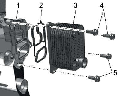
32.33. Oil cooler installation details
34. Installation is carried out in reverse order. Use new seals.