



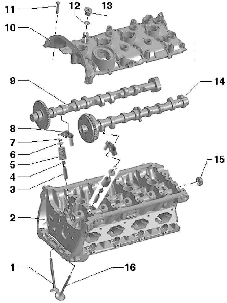
31.1 Timing belt parts 1. Exhaust valve, machining is not allowed, only lapping; 2. Cylinder head; 3. Valve guide bushing; 4. Oil deflector cap; 5. Valve spring; 6. Spring plate 5; 7. Split valve lock crackers; 8. Rocker arm with hydraulic valve clearance compensator; 9. Exhaust camshaft; 10. Cylinder head cover; 11. Bolt, to be replaced, 8 Nm, then tighten to an angle of 90°; 12. O-ring, subject to replacement, lubricate with engine oil; 13. Cork; 14. Intake camshaft; 15. The cover is replaceable and is pressed in without sealant to a depth of 1-2 mm; 16. Inlet valve, machining is not allowed, only lapping
Removal and installation camshafts and cylinder head cover
Note: Machining the upper surface of the cylinder head and the lower surface of its cover is not permitted, since the camshaft bearings are built into the cylinder head and its cover.
2. Remove the sound insulation under the engine compartment, as well as the right front wheel arch liner (see Chapter 11).
3. On models with an additional heater, loosen the clamp (1 in illustration 15.12), unscrew the bolt (2) and remove the additional heater muffler.
4. Unscrew the bolts (arrows in illustration 25.4), lift the clamps (1 and 2) and remove the air pressure tube.
5. Remove the upper timing chain cover (see Section 27).
6. Follow the steps in paragraphs 28-33 Section 30.
7. Remove the air cleaner (see Chapter 4).
8. Disconnect the vacuum line (3 in the illustration) at the connection point (1), disconnect the connector (2) of the CMP "G40" sensor and unscrew the coolant line fastener (6) from the vacuum pump. Remove the high-pressure fuel pump (7, see Chapter 4), vacuum pump (5, see Section 30), ignition coils (4, see Chapter 5) and PCV oil separator GD).
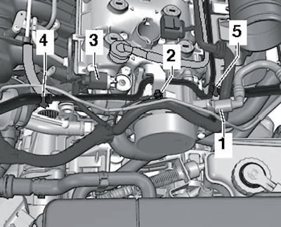
31.8. Details on the cylinder head cover
9. Remove the cylinder head cover mounting bolts in the following sequence: (1-6 in the illustration) and remove the lid. Remove the camshafts. Take precautions to prevent dirt and sealant residue from entering the cylinder head.
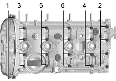
31.9. Sequence of unscrewing the cylinder head cover bolts
10. Remove any remaining sealing material from the mating surfaces of the cylinder head and its cover, and then clean them from oil and grease. It is recommended to use a chemical remover to remove sealant and grease.
11. Make sure that piston #1 is at TDC and the rocker arms are seated correctly on the ends of the valves.
12. Lubricate the bearing surfaces of the camshafts and place them in the cylinder head so that the grooves are located vertically opposite each other and facing each other (see illustration).
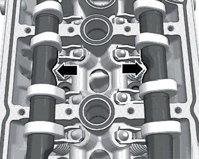
31.12. Installation position of camshafts
13. Apply a bead of G154 103A1 silicone sealant with a diameter of 2-3 mm to the cylinder head cover, as shown in the illustration. After applying the sealant, the cover should be installed within no more than 5 minutes. The sealant layer should not be too thick, otherwise excess sealant will be squeezed inward and can lead to clogging of the oil channels.
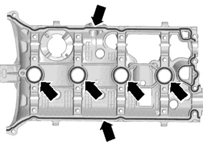
31.13. Sealant application scheme
14. Install the cylinder head cover and tighten the new bolts evenly in the following sequence: (6-1 in Illustration 31.9) in several approaches: first by hand, then with a force of 8 Nm, and then pull them to an angle of 90°.
15. Using the T10174 tool, install the new cover (1 in the illustration) without sealant to a depth of (a) - 1-2 mm.
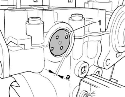
31.15. Installing the cover on the end of the cylinder head
16. Perform the actions described in paragraphs 44-47 Section 30.
17. Further installation is carried out in reverse order.
Replacing valve stem seals without removing the cylinder head
18. Remove the camshafts (see subsection above).
19. Remove the spark plugs (see Section 14 Chapter 1).
20. Remove the rocker arms and place them on a clean surface so that they can then be installed in their original positions.
21. Fit the guide plate VAS5161/19B to the cylinder head using the bolts VAS5161/12 as shown in the illustration.
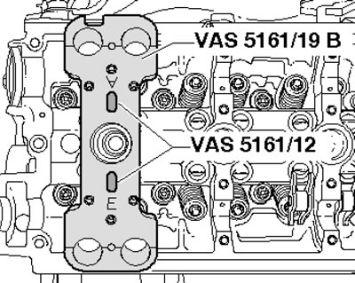
31.21. Installing the guide plate
22. Set the piston of the corresponding cylinder to the bottom dead center position.
23. Screw the T40012 adapter into the spark plug hole and apply air under a pressure of at least 6 bar, and then, if the valve lock crackers are jammed, hit them with a plastic hammer VAS5161/3 (see illustration).
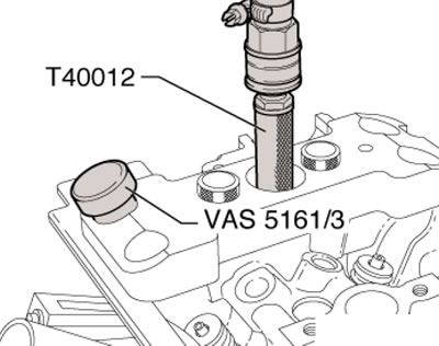
31.23. Air supply
24. On the intake side, screw the toothed part VAS5161/6 with the fork VAS5161/5 into the central threaded hole of the plate VAS5161/19B (see illustration). Then insert the VAS5161/8 cartridge into the VAS5161/19B plate and attach the VAS5161/2 pressure fork to the VAS5161/6 component.
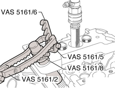
31.24. Intake side fittings
25. On the exhaust side, screw the toothed part VAS5161/6 with the fork VAS5161/5 into the outer threaded hole of the plate VAS5161/19B (see illustration). Press the VAS5161/8 cartridge down and at the same time turn its knurled screw to the right until the ends are locked in the crackers. Move the knurled screw back and forth slightly to press the crackers and trap them in the cartridge. Release the pressure fork VAS5161/2 and remove the cartridge VAS5161/8. Remove the plate VAS5161/19B.
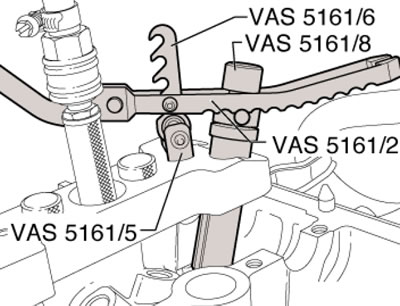
31.25. Outlet side fittings
26. Pull out the oil deflector caps using the MP1-230 puller (see illustration).
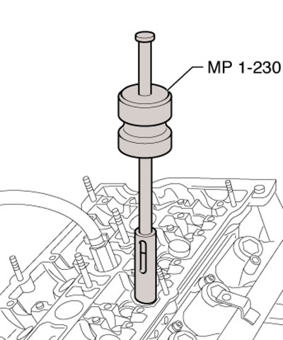
31.26. Removing the oil seal
27. If it is not possible to use the MP1-230 puller due to space limitations, knock out the pin (arrow on the illustration) and remove the striker.
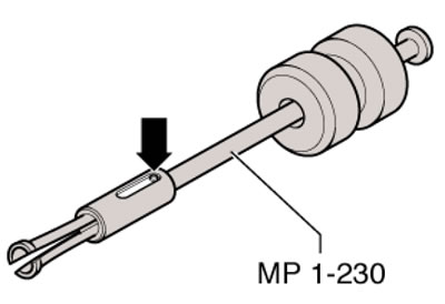
31.27. Modification of MP1-230 puller
28. Place the lower part of the MP1-230 puller on the oil deflector cap, insert a punch into its hole (1 in the illustration) and pull the cap in the direction of the arrow.
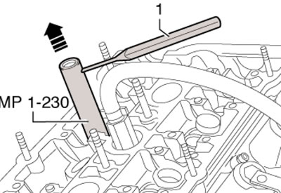
31.28. Removing the oil deflector cap with a modified puller
29. To avoid damaging the new oil deflector cap (In the illustration), put the plastic sleeve (A) on it. Lubricate the sealing lip of the cap, install it in the MP1-233 device and carefully slide it onto the valve stem. Remove the plastic sleeve (A), insert the valve spring and its plate.
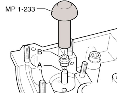
31.29. Installing the oil deflector cap
30. On the intake side, move the VAS5161 tool to the position shown in Figure 31.24.
31. On the exhaust side, move the VAS5161 tool to the position shown in Figure 31.25.
32. If the crackers have been removed from the installation cartridge, insert them into the VAS5161/18 tool (see illustration), and then press the VAS5161/8 cartridge into it from above and grab the crackers.
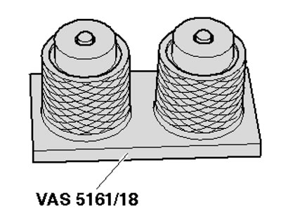
31.32. Installation tool VAS5161/18
33. Press the cartridge VAS5161/8 downwards with the pressure fork VAS5161/2 and turn the knurled screw of the cartridge back and forth while pulling it upwards. Release the pressure created by the fork while still pulling the screw upward.
34. Remove tool VAS5161.
35. Further installation is carried out in reverse order.