



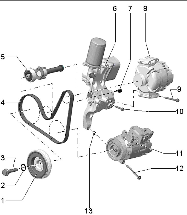
24.1. Auxiliary drive parts 1. Crankshaft pulley; 2. Sealing ring, subject to replacement; 3. Pulley bolt 1, to be replaced, 150 Nm, then tighten to an angle of 90°; 4. Auxiliary drive belt; 5. Belt tensioner 4; 6. Auxiliary bracket, with oil filter and oil cooler; 7. Bolt, 10 Nm; 8. Generator; 9. Bolt, 23 Nm; 10. Bolt, subject to replacement, 20 Nm, then tighten to an angle of 90°; 11. Refrigeration unit compressor; 12. Bolt, 25 Nm; 13. Centering sleeve for compressor 11
Auxiliary drive belt
2. Loosen the connection on the back of the EVAP canister, separate the canister from the bracket upward and set it aside without disconnecting the hoses (see illustration).
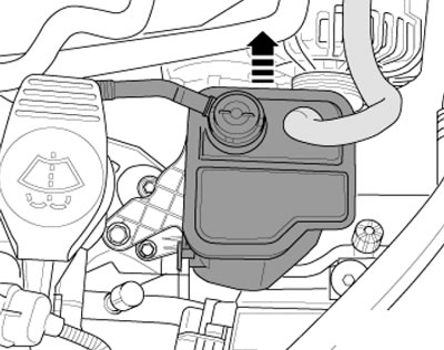
24.2. Right air hose
3. If the belt being removed is intended to be reused, mark the direction of its movement on it. Remove the accessory drive belt.
4. Turn the belt tensioner in the direction of the arrow (see illustration) and lock the tensioner with the T10060A locking pin. Remove the drive belt.
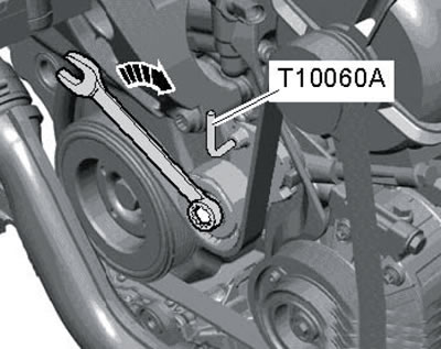
24.4. Loosening the belt tension
5. Before installing the belt, make sure that the compressor and generator fasteners are securely tightened.
6. Place the drive belt first on the crankshaft pulley, then on the compressor and generator pulleys. If a used belt is being installed, the marks on it must face the direction of its rotation when the engine is running.
7. Slightly turn the belt tensioner from underneath in the direction of the arrow (see illustration 24.4) and remove the locking pin T10060A to tighten the belt. Make sure the belt is seated correctly on the pulleys.
Drive belt tensioner
8. Remove the sound insulation under the engine compartment, as well as the right front wheel arch liner (see Chapter 11).
9. Loosen the swing support fasteners in the sequence (1-3 in illustration 5.21) and take it off.
10. Unscrew the bolt (2 in illustration 23.26) on the bracket of the coolant circulation pump "V51".
11. On models with additional heating, loosen the clamp (1 in illustration 15.12), unscrew the bolt (2) and remove the additional heater muffler.
12. Remove the drive belt (see subsection above).
13. Remove the expansion tank cap.
14. Install the T30099 support as shown in the illustration and relieve the right engine support. Loosen the bolts (2 in illustration 23.21a) right engine mount bracket and lower the engine by approximately 50 mm (measurement on support).
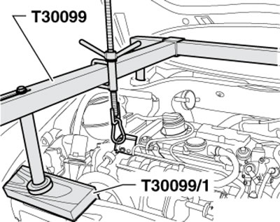
24.14. Unloading the right engine support
15. Release the electrical wiring tube (arrow on the illustration), unscrew the bolt (1) and remove the drive belt tensioner from the accessory bracket.
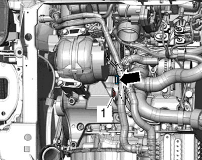
24.15. Removing the drive belt tensioner
16. Installation is carried out in reverse order. When installing the tensioner (1 in the illustration) insert it into the auxiliary bracket (3) and tighten the bolt (5). The protrusion (2) must fit into the hole in the auxiliary bracket. After installation, adjust the position of the supports (see Section 23).
[The original can be viewed on Skodabook.ru]
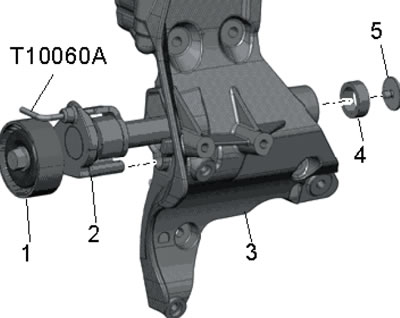
24.16. Drive belt tensioner installation details 1. Tensioner roller; 2. Tensioner with centering protrusion; 3. Auxiliary bracket; 4. Centering sleeve; 5. Bolt
Auxiliary bracket
17. Drain the coolant (see chapter 3).
18. Remove the accessory drive belt (see subsection above).
19. Remove the generator (see Chapter 5).
20. Remove the air conditioning compressor (see Chapter 3), without disconnecting the refrigerant lines, and hang it off to the side on the hood latch holder with a wire. Avoid bending, twisting or stretching refrigerant lines.
21. Unscrew the bolt (arrow on the illustration) guide tube of the dipstick, unscrew the bolts (1-5) and remove the auxiliary bracket from the water pump housing.
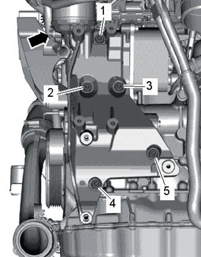
24.21. Auxiliary bracket mounting bolts
22. Prepare new sealing rings, gaskets, and bolts that are tightened in several stages.
23. Lubricate the sealing rings (4 in the illustration) coolant G12++, insert the connection (2) into the water pump housing (3) and slide the auxiliary bracket (1) onto the connection (2).
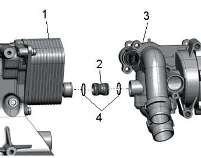
24.23. Connecting the water pump to the auxiliary bracket
24. First of all, screw in the bolt (4 in illustration 25.21) of the auxiliary bracket, and then tighten the bolts (1-5) in three stages: first by hand, then with a force of 20 Nm, and finally tighten them to an angle of 90°.
25. Install the remaining parts in the reverse order of removal.