



Removal
Note: The engine is removed from underneath the engine compartment downwards together with the transmission. All removed electrical wiring ties and clamps must be in their original places during installation. The electrical wiring and hoses should be routed in the same way as they were before removal. Therefore, you should remember or sketch/photograph the location of clamps, electrical wiring and hoses.
1. Relieve the pressure in the fuel supply system and remove the air cleaner (see Chapter 4).
2. Remove the top engine cover. To do this, unscrew the bolts (1 in the illustration), unhook the coolant hoses (2) and pull the cover up.
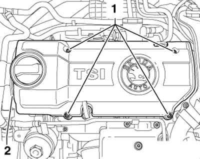
15.2. Upper Engine Cover Fastening Details
Note: When installing, tighten the bolts to 8 Nm.
3. Remove the air cleaner (see Chapter 4).
4. Follow the steps described in paragraphs 2-7 Section 5.
5. Disconnect the fuel supply line (1 in the illustration) and the hose (2) going to the EVAP canister by squeezing the retaining ring. Remove the hose (3) going to the adsorber from the solenoid valve No. 1 for purging the adsorber. Remove the canister upwards and unscrew the bolts (arrows) from the bracket. Remove the coolant hoses (4).
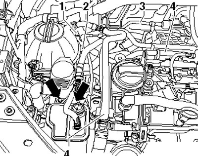
15.5. Removing the EVAP canister
6. Disconnect the coolant hose from the engine cooling system radiator, top left (see illustration).
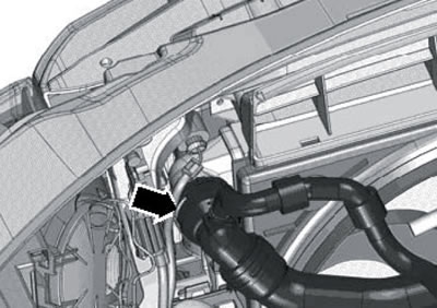
15.6. Upper radiator hose
7. Disconnect the coolant hoses (1 and 2 in the illustration) from the heater radiator.
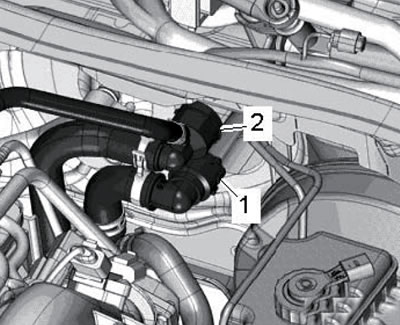
15.7. Hoses on the heater radiator
8. Unscrew the bolts and remove the turbocharger heat shield (see illustration).
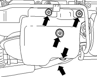
15.8. Fastening the heat shield
9. Release the nuts on the turbocharger (see illustration).
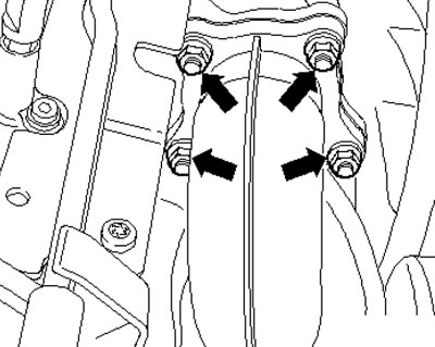
15.9. Nuts on the turbocharger
10. Remove the coolant pipe (2 in the illustration).
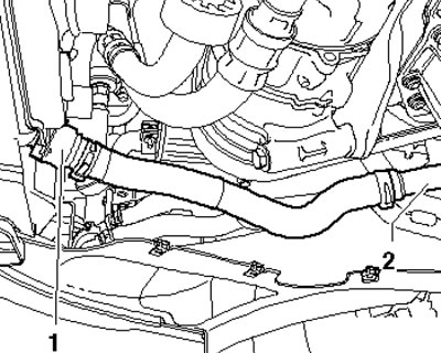
15.10. Coolant pipes
11. Disconnect the connector (1 in the illustration) sensor "G266" of engine oil level and temperature. Remove the bracket (2) for the G266 sensor wiring harness from the powertrain support.
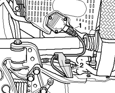
11/15 Wiring of the G266 sensor
12. On models with an additional heater, remove the coolant pipe and loosen the clamp (1 in the illustration), unscrew the bolt (2) and remove the outlet pipe of the additional heater.
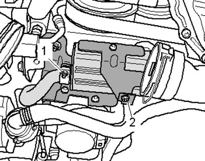
15.12. Removing the outlet pipe of the additional heater
13. Pull out the wiring (1 in the illustration) on the catalytic converter, disconnect the connectors (2), loosen the nuts (3) and remove the gasket. Remove the catalytic converter downwards.
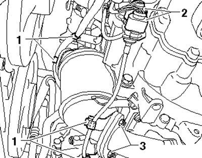
15.13. Removing the catalytic converter
14. Give the nuts (2 and 3 in the illustration) and remove the gasket. Unscrew the bolts (1 and 5) and remove the exhaust pipe with the bracket (4).
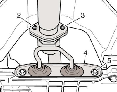
15.14. Removing the exhaust pipe
15. Loosen the clamp bolts (see illustration) and pull the intermediate exhaust pipe back. Remove or free all wiring from the transmission, alternator, and starter, as well as other engine wiring. Remove the vacuum and ventilation hoses from the engine.
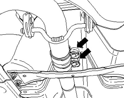
15.15. Exhaust pipe clamp
16. Disconnect the connector (1 in the illustration) thermal switch and radiator fan. Disconnect the engine wiring harness connector at the ECM (front connector).
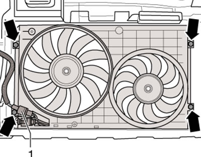
15.16. Radiator thermal switch and fan connector
17. Remove the wiring harness guide plate retainer (see illustration 5.15) and pull it up from the bulkhead near the expansion tank.
18. Open the entire engine wiring harness protection on the side member (see illustration 5.16). Open the other connections of the engine wiring harness, remove it, place it on the engine and secure it with clamps.
19. Loosen the swing support fasteners in the sequence (1-3 in illustration 5.21) and remove it. On models with a refrigeration unit, remove the accessory drive belt (see Section 36).
20. On models with DSG, remove the selector cable from it (see Chapter 7).
21. On models with a manual transmission, remove the gear shift mechanism and the clutch hydraulic actuator cylinder from it without opening the hydraulic circuit (see Chapter 6). Hang the slave cylinder to the side.
Note: After removing the clutch slave cylinder, do not depress the clutch pedal.
22. Set the hood lock holder to the service position (see Chapter 11).
23. Disconnect the connector (3 in the illustration) circulation pump of the coolant "V50". Loosen the clamps (arrows) and disconnect the coolant hoses. Unscrew the bolt (2) and remove the pump from the bracket. Remove the bolts (1) of the pump bracket from the cylinder block.
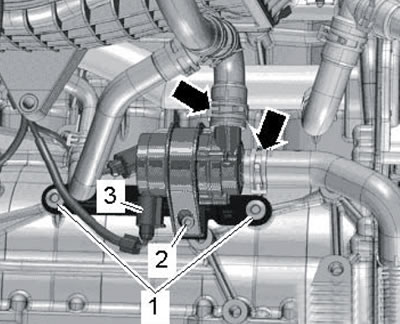
15.23. Removing the coolant circulation pump and its bracket
24. Remove the drive belt (see Section 16).
25. Disconnect the connector (1 in illustration 5.22) magnetic clutch of the compressor and unscrew the bolts (arrows).
Remove the A/C compressor without disconnecting the refrigerant lines from it and secure it to the hood latch bracket with wire so that the refrigerant lines are not stretched or kinked.
26. To lower the power unit, prepare the T40075A support with -/1, -/2 and -/3 (see illustration).
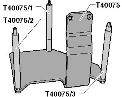
15.26. Device for removing the power unit
27. Screw the T40075/1 adapter into the cylinder block until it stops (see illustration).
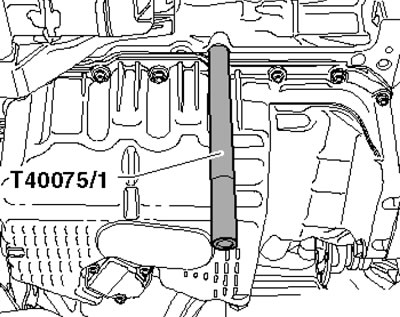
15.27. Adapter T40075/1
28. Place the T40075A support with adapters -/2 and -/3 on the cylinder block and secure the adapter -/1 with the bolt (3 in the illustration). Between the cylinder block and the T40075A support, install two M10 nuts (2) and secure the support by screwing in the M8x35 bolt (1) by hand. Tighten all support mounting bolts with a force of 20 Nm, install the VAG1383A jack under the T10416 support and slightly lift the power unit on it to relieve its supports.
(The original article can be found on the resource: SkodaBook.ru)
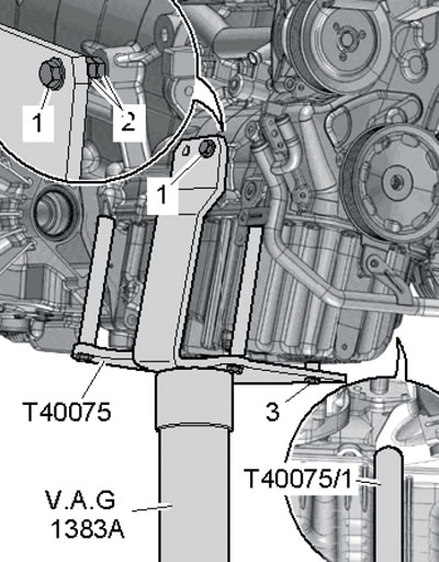
15.28. Installing the jack
29. Make sure all hoses and wiring between the engine, transmission and body are disconnected. Take the bolts from the stepladder (see illustrations) fastening the right and left brackets (on the engine and transmission).
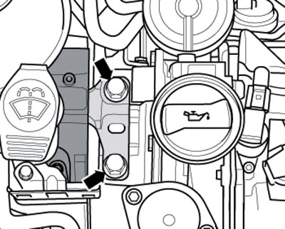
15.29a. Right powertrain support bracket bolts
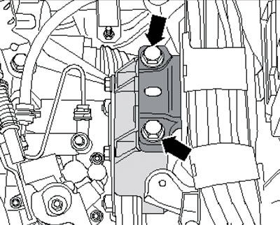
15.29b. Left powertrain support bracket bolts
30. Together with an assistant, pull the power unit as far forward as possible and carefully lower it from the engine compartment using a jack. Avoid damaging powertrain components and engine compartment components.
31. Secure the engine to the mounting stand and separate the transmission from the engine (see chapter 6 or 7).
Installation
Note: Place the hoses and wiring in the same position as they were before removal; install all clamps and ties back in their original places. Depending on the thread, tighten the fasteners with the following forces: M6 - 9 Nm, M7 - 13 Nm, M8 - 20 Nm, M10 - 40 Nm, M12 - 70 Nm.
32. Installation is carried out in reverse order. Please note the following features.
33. Use new self-locking nuts and bolts that require tightening to a certain angle. Use new seals and gaskets.
34. On models with manual transmission, clean the splines of the transmission input shaft and, if an old clutch disc is used, its splines. Remove any traces of corrosion and apply a very thin coat of G000 100 grease to the input shaft splines. Move the clutch disc on the shaft until the disc moves smoothly, then remove any excess grease. Check the clutch release bearing for wear; replace it if necessary. Make sure the clutch is centered (see Chapter 6).
35. On DSG models, replace the crankshaft needle bearing as described in Section 14.
Note: Press the bearing to a depth of (and in illustration 14.3b) - 2.0 mm.
36. Make sure the transmission centering bushings are inserted into the cylinder block. Secure the transmission to the engine (see chapter 6 or 7).
37. Secure the power unit to the transmission jack using the T40075A support, move it into the engine compartment and screw in the new power unit bracket mounting bolts by hand. Adjust the brackets and tighten the bolts that secure them (see subsection below).
38. Install the rocker support (see subsection below) and drive shafts (see Chapter 8).
39. Install the compressor and accessory drive belt.
40. Perform the actions described in paragraphs 36-43 Section 5.
Checking and adjusting the powertrain supports
41. The details of the support fastenings are shown on illustrations 5.44.
42. To check the installation of the bracket, measure the distance (and in the illustration) between the bracket and the support, - it should be 10 mm. The cast edge of the support (2) should be parallel to the support lever (1), and the distance (x) should be the same at the front and back. If the engine or transmission hits the side member when turning and the distance (a) is not 10 mm, adjust the bracket as described below.
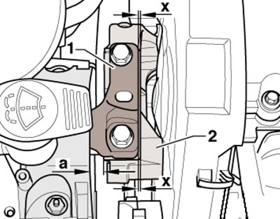
15.42. Checking the installation of the right bracket
43. Remove the battery and its holder (see Chapter 5).
44. Remove the expansion tank cap.
45. Install support T30099 (see illustration 5.48) and evenly unload the power unit supports by rotating both spindles.
46. Loosen the bolts (see illustration 15.29a) fastening the right bracket and slightly (no more than 1 turn) loosen the bolts (see illustration 15.29b) fastening the left bracket.
47. If the bracket bolts were not yet replaced when installing the engine, screw in the new bolts one by one.
48. Move the power unit using a lever installed between the support lever (1 in illustration 15.42) and support (2) so that the distance (a) is 10 mm and the distance (x) is the same at the front and back. Tighten the right support bolts (see illustration 5.44).
49. Make sure that on the transmission side the edges of the support (1 in illustration 5.52) and its support lever (2) are located parallel to each other. That is, the distance (x) must be the same on both sides of the support. Tighten the bracket mounting bolts (see illustration 5.44).
50. Install the remaining parts.