



Removal and installation
Note: The engine is removed from underneath the engine compartment downwards together with the transmission. All removed electrical wiring ties and clamps must be in their original places during installation. The electrical wiring and hoses should be routed in the same way as they were before removal. Therefore, you should remember or sketch/photograph the location of clamps, electrical wiring and hoses.
1. Remove the air cleaner (see Chapter 4).
2. Remove the PCV tube (1 in the illustration), unscrew the bolt (arrow) and remove the inlet pipe by loosening the clamp (2). Seal the turbocharger inlet port to prevent dirt from getting in.
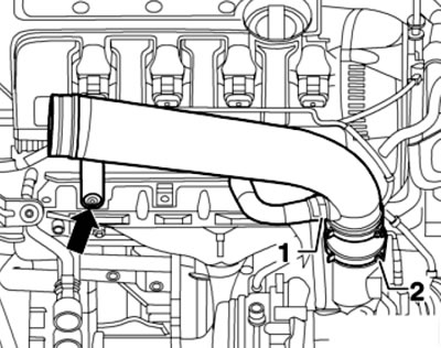
23.2. Removing the intake pipe
3. Remove the battery (see Chapter 5).
4. Remove the cover (2 in the illustration) mounting block, release the wire fastener (3), unscrew the bolts (arrows) and remove the battery mounting tray (1).
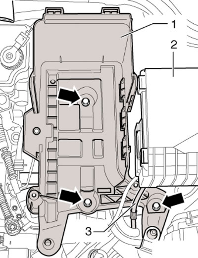
23.4. Removing the battery tray
5. Remove the front right wheel arch liner (see Chapter 11) and the right drive shaft (see Chapter 8).
6. Loosen the left drive shaft fastener to the transmission flange shaft and tie the drive shaft so that it does not hang down under its own weight.
7. Remove the exhaust pipe (see Chapter 4) and cardan shaft (on AWD models, see Chapter 8).
8. Remove the radiator fan shroud and drain the coolant (see Chapter 3). Disconnect the coolant hoses from the radiator, heater radiator and expansion tank.
9. Disconnect the engine wiring harness connector from the ECM (see Chapter 5).
10. Remove the wiring harness guide plate retainer (see illustration 5.15) and pull it up. Pull the rear left engine wiring harness out of the bulkhead near the expansion tank.
11. Open the wiring guide bracket (see illustration 5.16).
12. Disconnect the connector (1 in the illustration) and open the bracket (2) under the electrical wiring guide. Release the engine wiring harness to the ECM, disconnect all engine/body wiring harness connectors.
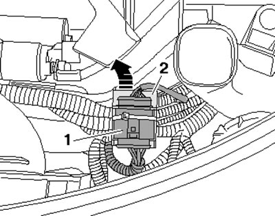
23.12. Connector (1) and bracket (2)
13. On models with DSG, remove the selector lever cable from it (see Chapter 7).
14. On models with a manual transmission, remove the gear selection and shift cables from it, remove the rack (1 in the illustration), remove the slave cylinder (arrows) of the clutch hydraulic drive and tie it to the side without opening the clutch hydraulic drive circuit.
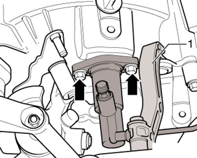
23.14. Rack (1) and fasteners (arrows) of the actuator cylinder
Note: Do not depress the clutch pedal after removing the clutch slave cylinder.
15. Remove the clamp (arrow on the illustration) protective cap (if available), disconnect the ground wire (1), disconnect the connector (2), pull back the protective cap and disconnect the B+ wire from the starter solenoid valve bracket.
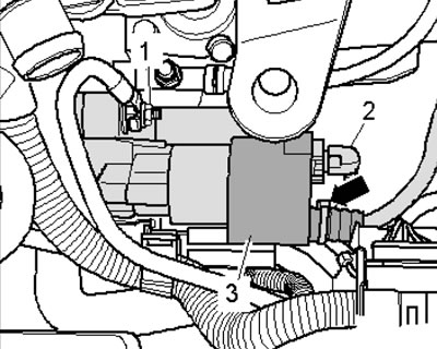
23.15. Starter Wiring Connections
16. Loosen the clamp (2 in the illustration), unscrew the bolt (4), disconnect the connector (arrow) and pull out the wiring. Loosen the bolt (1) and remove the pressure pipe in a downward direction.
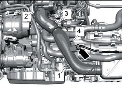
23.16. Pressure tube
17. Remove the right pressure hose (see illustration).
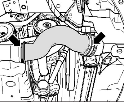
23.17. Right pressure hose
18. On models with additional heating, loosen the clamp (1 in illustration 15.12), unscrew the bolt (2) and remove the additional heater muffler.
19. Disconnect the connector (2 in the illustration) sensor "G83" of coolant temperature at the radiator outlet and connection (1).
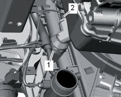
23.19. Sensor (2) of coolant temperature at the radiator outlet
20. Remove the fuel supply line (2 in illustration 17.13), pressing the retaining ring upwards, and collect the leaking fuel.
21. Loosen the bolts (see illustrations) brackets of the right and left engine mounts by no more than 1 turn.
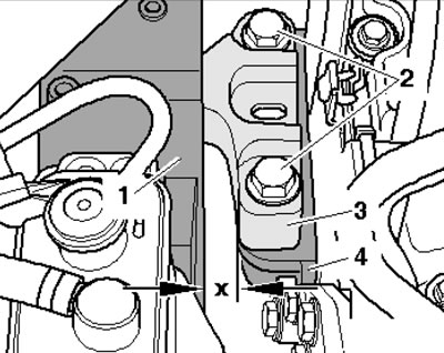
23.21a. Bolts (2) of the right engine bracket
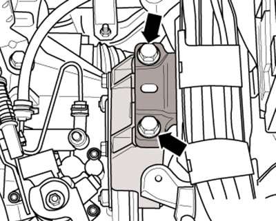
23.21b. Left engine bracket bolts
22. Remove the drive belt (see Section 24).
23. On models with a refrigeration unit, disconnect the connector (1 in illustration 5.22) compressor magnetic clutch and unscrew the bolts (arrows). Remove the air conditioning compressor without disconnecting the refrigerant lines from it and secure it to the hood lock holder with wire so that the refrigerant lines are not stretched or kinked.
24. Disconnect the connector (1 in illustration 15.11) sensor "G266" of engine oil level and temperature. Unhook the bracket (2) for the G266 sensor wiring harness from the holder on the powertrain support.
25. Remove/release all remaining wiring from the engine and transmission; disconnect the coolant, vacuum and ventilation hoses from the engine.
26. Remove the bolt (2 in the illustration) on the bracket of the coolant circulation pump "V51".
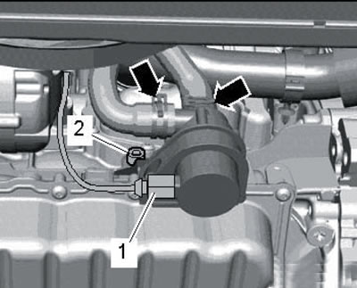
23.26. Circulation pump "V51"
27. Loosen the swing support fasteners in the sequence (1-3 in illustration 5.21) and take it off.
28. Secure the T10359 support to the cylinder block by tightening the bolt (1 in the illustration) into the hole for fastening the circulation pump "V51" with a force of 20 Nm. Insert the transmission jack VAG1383A into the support T10359 and support the engine to relieve its supports.
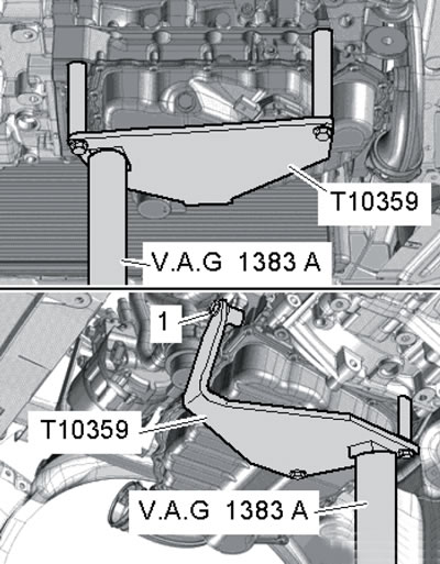
23.28. Devices for lifting the power unit
29. Make sure all hoses and wiring between the engine, transmission and body are disconnected. Take the bolts from the stepladder (see illustrations 23.21 a-b) fastening the right and left brackets (on the engine and transmission).
30. With the help of an assistant, slightly lower the power unit, pull it as far forward as possible and carefully lower it out of the engine compartment using a jack. Avoid damaging powertrain components and engine compartment components.
31. Secure the engine to the mounting stand and separate the transmission from the engine (see chapter 6 or 7).
32. Installation is carried out in the same way as on the 1.4 l engine (see Section 15). A description of the inspection and adjustment of the power unit supports is given in the subsection below.
Checking and adjusting the powertrain supports
33. The details of the support fastenings are shown in the illustration.
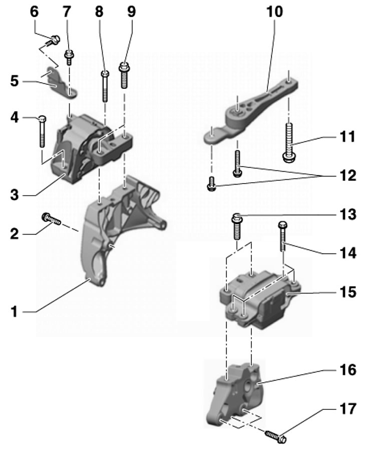
23.33. Powertrain support fastening parts 1. Support bracket 3; 2. Bolt, subject to replacement, 40 Nm, then tighten to an angle of 180°; 3. Right engine mount; 4, 8, 14. Bolt, subject to replacement, 40 Nm, then tighten to an angle of 90°; 5. Connecting piece; 6, 7. Bolt, subject to replacement, 20 Nm, then tighten to an angle of 90°; 9, 13. Bolt, subject to replacement, 60 Nm, then tighten to an angle of 90°; 10. Swing support, when removing, unscrew the bolts in the sequence 11-12, and when installing - in the sequence 12-11; 11. Bolt, subject to replacement, 100 Nm, then tighten to an angle of 90°; 12. Bolts, subject to replacement 40 Nm (strength class 8.8) or 50 Nm (strength class 10.9), then pull it to a 90' angle; on models with manual transmission "MQ350" (code "02Q") after thread repair it is allowed to use only bolts of strength class 10.9; 15. Left engine mount; 16. Support bracket 15; 17. Bolt
34. To check the installation of the bracket, make sure that the heads of both bolts (2 in illustration 23.21a) are parallel to the edge of the support arm (3), and the distance between the bracket (1) and the support (4) is 10-13 mm. If the engine or transmission hits the side member when turning and the distance (x) is not 10-13 mm, adjust the bracket as described below.
35. Remove the battery and its holder (see Chapter 5).
Information copied from the resource (SKODABOOK.ru)
36. Remove the expansion tank cap.
37. Install support T30099 (see illustration) and evenly relieve the power unit supports by rotating both spindles.
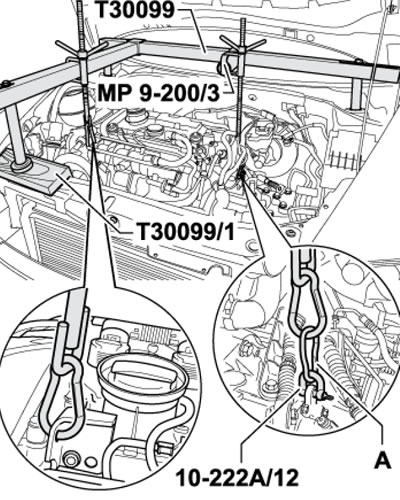
23.37. Device for unloading the power unit supports
38. Loosen the bolts (2 in illustration 23.21a) fastening the right bracket and slightly (no more than 1 turn) loosen the bolts (see illustration 23.21b) fastening the left bracket.
39. If the bracket bolts were not yet replaced when installing the engine, screw in the new bolts one by one.
40. Move the power unit using a lever installed between the support lever (3 in illustration 23.21a) and support (1) so that the heads of the bolts (2) are parallel to the edge of the support arm and the distance (x) is 10 mm. Tighten the bolts of the right support (see illustration 23.33).
41. Make sure that on the transmission side the edges of the support (1 in the illustration) and its support lever (2) are located parallel to each other. That is, the distance (x) must be the same on both sides of the support. Tighten the bracket mounting bolts (see illustration 23.33).
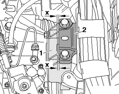
23.41. Checking the installation of the left support
42. Install the remaining parts.