



Contents: Clutch pedal sensor "G476" ⬇ Knee airbag holder with clutch pedal…⬇ Clutch pedal bracket ⬇ Eccentric spring ⬇ Master cylinder ⬇ Clutch pedal ⬇
1. The parts of the pedal assembly and clutch master cylinder are shown in the illustration.
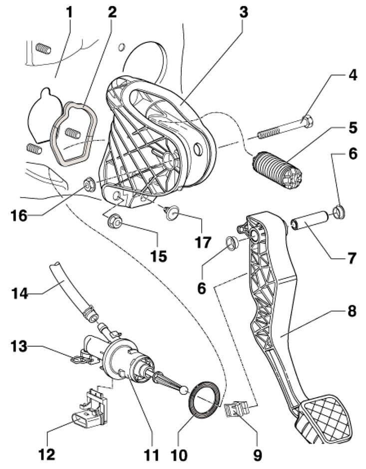
10.1 Clutch pedal assembly parts 1. Engine compartment bulkhead with bracket support 3; 2. Self-adhesive seal between the bracket and the bulkhead, replaceable, glued to the bracket; 3. Clutch pedal support bracket; 4. Bolt; 5. Eccentric spring; 6. Bearing bushing; 7. Pedal axle; 8. Clutch pedal; 9. Support; 10. Seal between cylinder 11 and bracket 3, subject to replacement; 11. Clutch master cylinder; 12. Clutch pedal position sensor "G476"; 13. Clutch hydraulic line retainer; 14. Plastic tube or rubber hose; 15. Self-locking nuts, 3 pcs., 25 Nm, subject to replacement; 16. Nut, 25 Nm, subject to replacement; 17. Clutch pedal stop
Clutch pedal sensor "G476"
2. Remove the air cleaner (see Chapter 4) and the battery with its holder (see Chapter 5).
3. Unhook sensor "G476" (arrow on the illustration) from the master cylinder, and then disconnect the sensor connector (4).
4. Installation is carried out in reverse order.
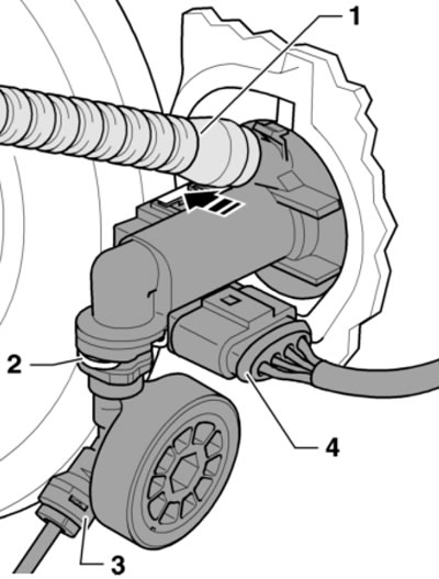
10.4. Removing the clutch pedal sensor
Knee airbag holder with clutch pedal support
5. The installation details of the knee airbag holder with the clutch pedal stand are shown in the illustration. Further references in this subsection refer to this illustration.
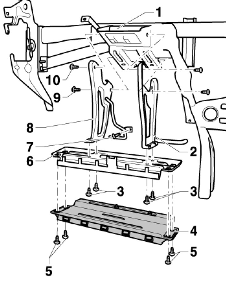
10.5. Knee airbag holder installation details with clutch pedal stand 1. Module holder; 2, 8. Cushion holder 4 with clutch pedal stand; 3, 9, 10. Bolts, 9 Nm; 4. Knee airbag; 5. Bolts, 7 Nm; 6. Pillow stand 4; 7. Bolt for fastening the air duct to the left footwell, 1.5 Nm
6. To remove the holder (2, 8), unscrew the bolts (9 and 10).
7. To unscrew the upper bolt (10), it is necessary to remove the instrument cluster (see Chapter 12).
8. To unscrew the lower bolt (9), it is necessary to remove the lower part of the instrument panel on the driver's side (see Chapter 11), unscrew the bolt (7), remove the knee airbag, block "J519" with the relay holders above and below it, release the wiring.
Clutch pedal bracket
9. Remove the sensor "G476" (see subsection above), without disconnecting the electrical wiring from it.
10. Place a cloth under the connection to collect brake fluid, disconnect the return hose from the clutch master cylinder (1 in illustration 10.4) and seal it immediately.
11. Pull out the retainer with a screwdriver (2 in illustration 10.4) and disconnect the plastic tube (3) from the master cylinder.
12. Remove the knee airbag bracket from the clutch pedal stand (see subsection above).
13. Place a cloth on the floor covering in the driver's footwell to collect the brake fluid.
14. Give the nuts (2 in the illustration) and remove the bracket (1).
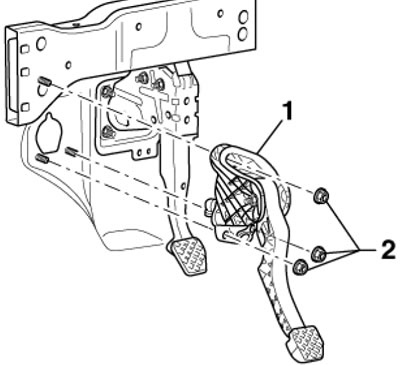
10.14. Bracket fastening
15. Installation is carried out in reverse order. Use new bracket mounting nuts; tighten them to 20 Nm.
Eccentric spring
16. Move the driver's seat back and raise the steering column.
17. Remove the knee airbag bracket from the clutch pedal stand (see the relevant subsection above).
18. Remove the steering column from the steering gear (see Chapter 10).
19. Give the nut (1 in the illustration) and pull out the axle bolt (5) to detach the clutch pedal (1) from the bracket (3).
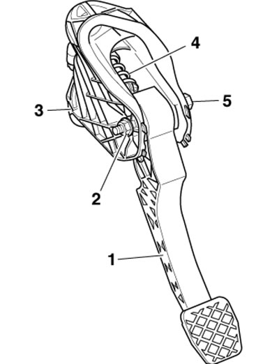
10.19. Removing the spring
Note: The pedal remains hanging on the working cylinder rod. Tilt the pedal down slightly and remove the eccentric spring (4) from the bracket.
20. Insert the eccentric spring (2 in the illustration) into the bracket from above, holding its end in the installation position with the T10178 device. Insert the axle into the spring, lightly press the clutch pedal (1), finally insert the axle and tighten the new self-locking nut with a force of 25 Nm.
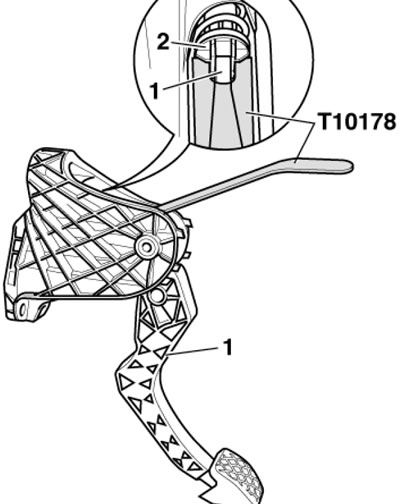
10.20. Installing the spring
21. Secure the steering column to the steering gear using new fasteners.
Master cylinder
22. Remove the pedal bracket (see the relevant subsection above).
23. Release the master cylinder rod support using T10005 pliers (see illustration).
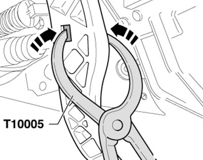
10.23. Releasing the master cylinder rod holder
24. Insert the spacer (And in the illustration) 40mm long between the pedal and the stopper and press the pedal into the spacer. Release the locking tab (B) and pull the master cylinder out of the bracket in the direction of the arrows (1 and 2).
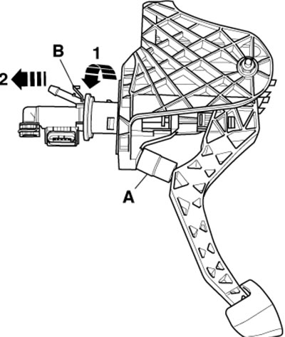
10.24. Separating the master cylinder from the clutch pedal
25. Pull the pedal back completely, connect the support (2 in the illustration) to the rod (1) of the master cylinder.
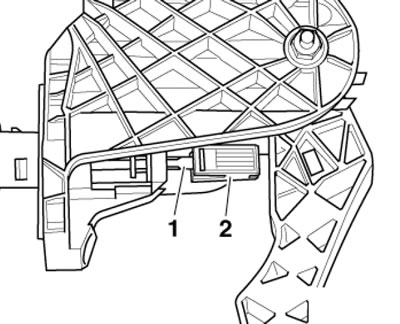
10.25. Installing the support on the rod
26. Insert the spacer (And in the illustration) 40mm long between the pedal and the stopper and press the pedal into the spacer. Hook the master cylinder into the bracket in the direction of the arrows (1 and 2).
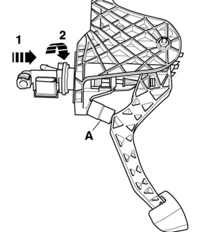
10.26. Fixing the cylinder in the bracket
27. Press the rod (1 in the illustration) master cylinder in the direction of the arrow until the support (2) is fixed in the clutch pedal with a distinct sound.
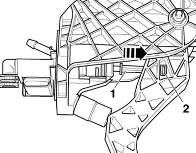
10.27. Fixing the cylinder in the pedal
28. Install the pedal bracket.
Clutch pedal
29. Remove the eccentric spring (see paragraphs 16-19).
30. Release the master cylinder rod holder using T10005 pliers (see illustration 10.23) and remove the clutch pedal.
31. Installation is carried out in reverse order. The process of connecting the pedal to the master cylinder rod is described in the subsection above.