
Note. After disconnecting and then connecting the wire connecting the battery terminal to ground (corps) vehicle, some additional work needs to be done.
1. Remove, if necessary, the upper decorative engine cover.
2. Remove the battery assembly (for details, see the relevant section in chapter Engine electrical equipment).
3. Remove the air filter assembly (for details, see the relevant section in chapter Intake and exhaust system).
4. Remove the engine control unit from the front wall of the body separating the engine compartment from the passenger compartment, if the master cylinder of the clutch control amplifier is not accessible.
5. Place a rag under the master cylinder of the clutch control amplifier.
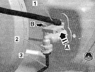
6. Disconnect compensation hose (1) from the master cylinder of the hydraulic clutch release drive, block it with a suitable device, e.g. locking device -T10249/1-.
Note.
- Do not use pipe clamp -MP7-602- as this could damage the compensation hose (1).
- When carrying out the following work, make sure that no brake fluid gets on the stringer or gearbox. If this happens, it is necessary to thoroughly clean such places.
7. Pull out the safety clip as far as it will go (2) on the clutch booster master cylinder as shown in the figure below.
Note. safety bracket (2) it is possible to pull out from some of the main cylinders of the clutch drive control amplifier also from the side.
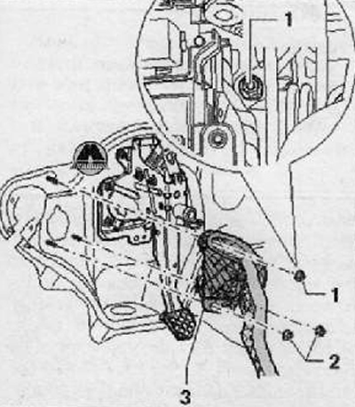
8. Remove the pipe and hose line (3) from the hydraulic clutch release master cylinder, as shown in the figure below. Plug it up.
Vehicles with Start-Stop system
9. Unclip the clutch pedal position sensor -G476- on the clutch booster master cylinder (arrow A) And (arrow B), as shown in the figure below.
10. Remove the clutch pedal position sensor from the hydraulic clutch release master cylinder with plug connectors attached.
Continuation for all cars
Note. When working in the footwell, protect floor mats from escaping brake fluid with a rag.
11. Remove the air duct nozzle to the footwell (for details, see the relevant section in chapter Heating, ventilation and air conditioning system).
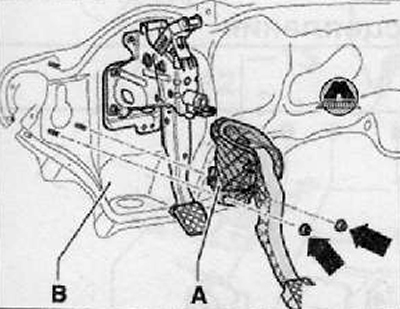
12. Unscrew the fastening bolts (arrows) and remove the safety support (A), if available, as shown in the figure below.
13. Set the steering wheel to its highest position.
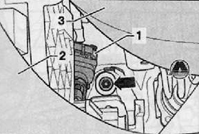
14. Remove clutch pedal switch -F36- (1), shown in the figure below.
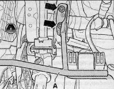
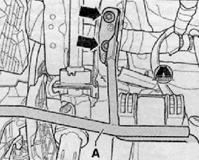
15. Loosen upper lock nut arrow) mounting bracket as shown in the figure below. To do this, install through the hole between the instrument panel (2) and the lower facing of a steering shaft (3) nut extension as shown in the figure below.
16. Loosen both lower lock nuts (arrows), shown in the figure below.
17. Remove mounting bracket (A) from the front wall of the body, separating the engine compartment from the passenger compartment (IN), as shown in the figure below.
Installation
Note. Install self-locking nuts (I) And (2) mounting bracket fixings (3) on the front wall of the body that separates the engine compartment from the passenger compartment, as shown in the figure below.
1. Installation is carried out in the reverse order, and the following instructions must be observed:
2. Install clutch pedal switch -F36-.
3. Install the safety support (A), if it is available. To do this, tighten the fixing screws to the required tightening torque (arrows), as shown in the figure below.
4. Install the duct nozzle in the footwell (for more details, see the relevant section in chapter Heating, ventilation and air conditioning system).
Vehicles with Start-Stop system
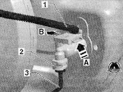
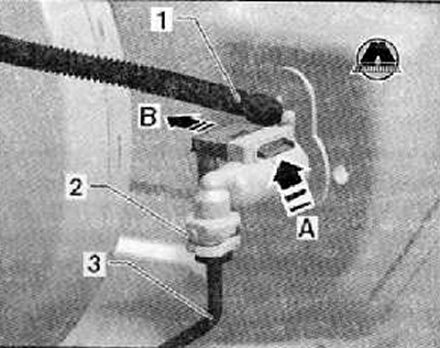
5. Fit the clutch pedal position sender -G476- with the electrical wiring harness plug connected to the hydraulic clutch release master cylinder as far as it will go. The clutch pedal position sensor should enter a fixed position (arrow A), shown in the figure below.
6. Engagement of the clutch pedal position sensor should be checked by pulling (arrow B).
Continuation for all cars
7. Press in the pipe and hose line (3) to the connection point of the hydraulic clutch release master cylinder so that the safety clip (2) came into a fixed position with a characteristic click.
8. Install a supplementary hose on the master cylinder of the clutch drive control amplifier (1), as shown in the figure below. The correct entry into the fixed position should be verified by pulling the wire.
10. To remove air from a hydraulic drive of deenergizing of coupling.
11. Install the engine control unit on the front wall of the body, separating the engine compartment from the passenger compartment, if it is removed.
12. Install the battery (for details, see the relevant section in chapter Engine electrical equipment).
13. Install the air filter housing assembly (see the relevant section in chapter Intake and exhaust system).