



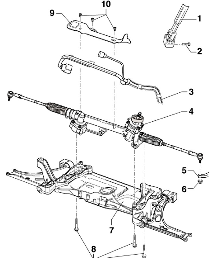
16.1. Steering gear installation details (using the example of models with an aluminum subframe) 1. Hinge; 2. Bolt M8x32, subject to replacement, 30 Nm; 3. Electrical wiring; 4. Steering gear, with steering column control unit "J500" and steering wheel angle sensor "G85"; 5. Steering knuckle; 6. Self-locking nut, subject to replacement, 20 Nm, then tighten to an angle of 90°; 7. Subframe with consoles; 8. Bolt M10x76, subject to replacement, 50 Nm, then tighten to an angle of 90°; 9. Heat shield; 9. Bolt, 6 Nm
2. Set the front wheels to the straight-ahead position and lock the steering column.
3. Disconnect the negative cable from the battery.
4. Remove the screws (see illustration 5.2) and remove the cover behind the pedals.
5. Unscrew the bolt (1 in illustration 5.3) and disconnect the joint (2) from the steering column.
6. Remove the front wheels.
7. Loosen the tie rod end nut on the steering knuckle, leaving it screwed on a few turns. Then press the tie rod end joint out of the steering knuckle using tool #3287A (see illustration 5.7), finally loosen the nut and separate the steering rod end from the steering knuckle.
8. Remove the sound insulation under the engine compartment (see Chapter 11).
9. Disconnect the anti-roll bar from its strut. If equipped, disconnect the front suspension height sensor connector.
10. On both sides of the car, loosen the nuts (see illustration 4.5 Chapter 8) and separate the ball joint from the front suspension arm.
11. Remove the bolts (14 in illustration 3.11) and disconnect the rocker support from the transmission. Remove the exhaust system bracket from the subframe and loosen the bolts (3, 6, 11 and 16) steering gear and stabilizer, and secure the subframe with consoles (see Section 3).
12. Support the subframe with a transmission jack, after placing a wooden block between them (1 in illustration 3.12).
13. Loosen the bolts (4 and 5 in illustration 3.11) and slightly lower the subframe with consoles, watching the wiring.
14. Remove the bolts (arrows in the illustration) and remove the heat shield (1) above the steering gear.
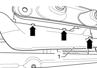
16.14. Heat shield mounting bolts
15. Remove the electrical wiring guide from the subframe (see illustration). Disconnect the wiring at the remaining mounting points on the steering gear. Disconnect the steering gear wiring connectors. Carefully lower the steering gear onto the jack.
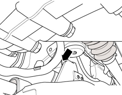
16.15. Electrical wiring guide
16. Installation is carried out in reverse order. The steering gear threaded bushings must be installed in the previous console holes. White diaphragm (see illustration) must be clean and undamaged, clean it if necessary. Finally, apply the basic settings for the G85 steering wheel angle sensor (using the diagnostic connector, see Chapter 5). If a new steering gear is installed, additionally adapt the power steering control unit "J500" and apply the basic settings to it.