



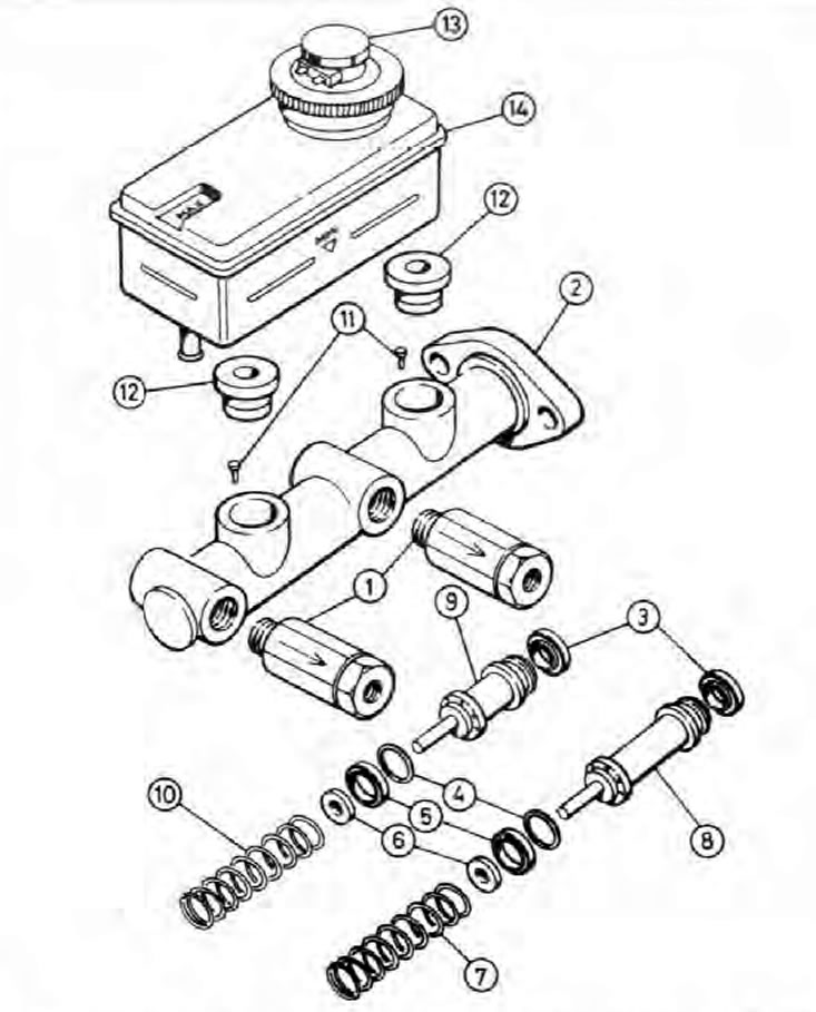
Fig. 9.5. Master cylinder components (early modification)
1. Brake pressure control valves (hatchback, Station Wagon and Van models only); 2. Master cylinder; 3. Piston seal; 4. Washer; 5. Piston cuff; 6. Spring support; 7. Primary piston spring (wire diameter 1.6 mm); 8. Primary piston; 9. Secondary piston; 10. Secondary piston spring (wire diameter 1.8 mm); 11. Locking pin; 12. Compaction; 13. Filler cap and liquid level sensor; 14. Feed tank.
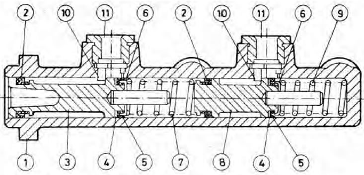
Fig. 9.6. Master cylinder (early modification) in section
1. Master cylinder; 2. Piston seal; 3. Primary piston; 4. Washer; 5. Piston cuff; 6. Spring support; 7. Primary piston spring (wire diameter 1.6 mm); 8. Secondary piston; 9. Secondary piston spring (wire diameter 1.8 mm); 10. Locking pin; 11. Compaction.
Note: Before proceeding, please refer to the note given at the beginning Chapters 9.
Removal
1. Remove the master cylinder reservoir cap, disconnect the wiring harness connector from the brake fluid level sensor and pump the fluid out of the reservoir. Alternatively, open any convenient bleeder nipple and gently press the brake pedal several times (see Chapter 9).
Note: Do not suck out the liquid by mouth as it is poisonous: use a syringe or an old rubber bulb.
2. Unscrew the connecting nuts and separate the metal brake pipes (see Chapter 10). Try to keep fluid loss to a minimum and wash away any spilled liquid as quickly as possible.
3. Unscrew the two nuts securing the master cylinder to the vacuum booster unit and remove the cylinder (see photo).
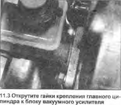
Bulkhead
Note: Before you start overhauling the cylinder, check the availability of the required repair kit of parts and other necessary components and their prices, compare them with the price of a new or already rebuilt master cylinder in a workshop, and only then decide whether overhaul is advisable. In addition, read the description of the procedure to the end and prepare all the required tools and devices.
All models
4. Remove the master cylinder from the engine compartment and clean it thoroughly. Unscrew the brake pressure control valves where there are (see Chapter 12).
5. Press the reservoir away from the master cylinder and remove its two seals from the cylinder body holes.
6. The procedure for overhauling the modified version of the master cylinder featured on models produced since 1992 is slightly different from this point onwards. Identify the cylinder to be removed using Fig. 9.7 and proceed as described in the appropriate sub-chapter.
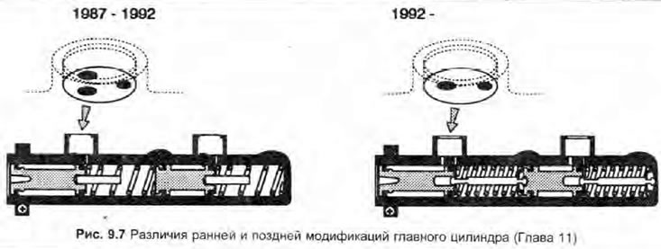
Models produced from 1987 to 1992.
7. Press the primary piston into the cylinder as far as possible and remove the piston retaining pins from the reservoir inlet ports by turning the assembly upside down and tapping it on a clean surface.
8. Keeping note of the order of removal and orientation of each component, remove the piston assemblies with their springs and seals. Tap the assemblies on a clean wooden surface to loosen them from the cylinder. If necessary, clamp the master cylinder in a soft-jawed vice and blow low-pressure compressed air through the secondary port to aid in removing the secondary piston assembly.
Warning: Be careful, the piston may jump out of the cylinder with some acceleration.
9. Clean all components thoroughly using only methyl or isopropyl alcohol, or clean brake fluid. Never use mineral solvents such as gasoline or kerosene for this purpose - they will damage the rubber components of the brake hydraulic system. Dry the components using compressed air or a clean, dense (lint-free) cloth.
10. Inspect all components and replace any that are worn or damaged. Pay particular attention to the cylinder bore and pistons - the complete cylinder assembly should be replaced if they are scratched, worn or corroded. If there is any doubt about the condition of the assembly or any of its components, replace as appropriate (see Note given in Chapter 1). Make sure that the cylinder inlet and bypass holes are not clogged.
11. If the assembly is suitable for further use, purchase the components necessary to assemble it. Be sure to replace all seals and rubber bearing cups - they should never be reused.
12. When assembling, soak the pistons and new bearing cups and seals with clean brake fluid. Apply clean fluid to the cylinder bore walls.
13. Install the new components into the grooves of the corresponding pistons without using any tools.
14. Insert the pistons into the cylinder using a twisting motion to avoid jamming the sealing lips. Make sure all components are installed in the correct order and oriented correctly.
15. Press the secondary piston assembly completely into the caliper cylinder using a clean metal rod, then install the lock pin.
16. Install the primary piston assembly and its locking pin.
17. Insert new seals into the cylinder bores, then install the reservoir and, where necessary, the brake pressure regulating valves.
18. Install the master cylinder into the engine compartment.
Models produced since 1992.
19. Tap the cylinder lightly on a clean wooden surface to release the piston assemblies, along with their springs and seals. Note the order of removal and the orientation of each component. The piston assemblies are held in place on these models only by the vacuum booster unit; if you can't get them out, use low pressure compressed air (see point 8 above).
20. Disassemble, clean, inspect and prepare components for assembly as described in steps 9-13 above.
21. Install the springs on the appropriate tappets and secure them by locking their bearings in the working position. Insert the spring and piston assemblies into the cylinder, ensuring that all components are installed in the correct order and correctly oriented. Use a twisting motion to avoid jamming the sealing lips.
22. Insert new seals into the cylinder bores, then install the reservoir and, where necessary, the brake pressure regulating valves.
23. Install the master cylinder into the engine compartment.
Installation
24. Install in the reverse order of removal, paying attention to the following:
- a) Install the master cylinder onto the booster block, aligning the primary piston rod located in the booster with the piston itself in the master cylinder.
- b) Tighten the master cylinder mounting nuts to the specified tightening torque Specifications.
- c) Fill the master cylinder reservoir with new fluid and bleed the system (see Chapter 9). Check the system joints for leaks.
- d) If a new master cylinder has been installed (or the old one was completely drained of liquid), bleed the cylinder by separating the metal tubes from it one by one (front first) and gently pressing the brake pedal until the brake fluid flowing out of the cylinder is free of air bubbles. Place a rag under the flowing stream to collect the fluid.
- e) In particularly difficult cases, disconnect the tubes, plug the exposed holes with your fingers, then open each one in turn when the brake pedal is pressed, and plug it again when the pedal is released, thus forcing fluid from the reservoir into the cylinder. Once the master cylinder has been bled of air, install and tighten all the couplings securely, then proceed with the normal bleeding procedure.