



Assembly diagram of the door lock
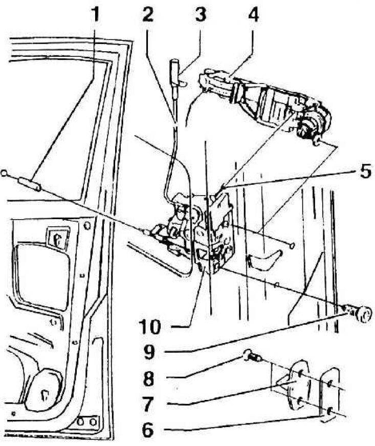
1 – traction cable for control from the inside, suspended from the locking part of the outer handle; 2 – safety button rod 3 – safety button (screwed on); 4 – internal locking part of the outer handle; 5 – pull cable for controlling the outer handle (suspended inside the outer handle); 6 – lining; 7 – eye of the lock; 8 – 30 Nm; 9 – 30 Nm; 10 – internal door lock
Material published on the website (SkodaBook)