
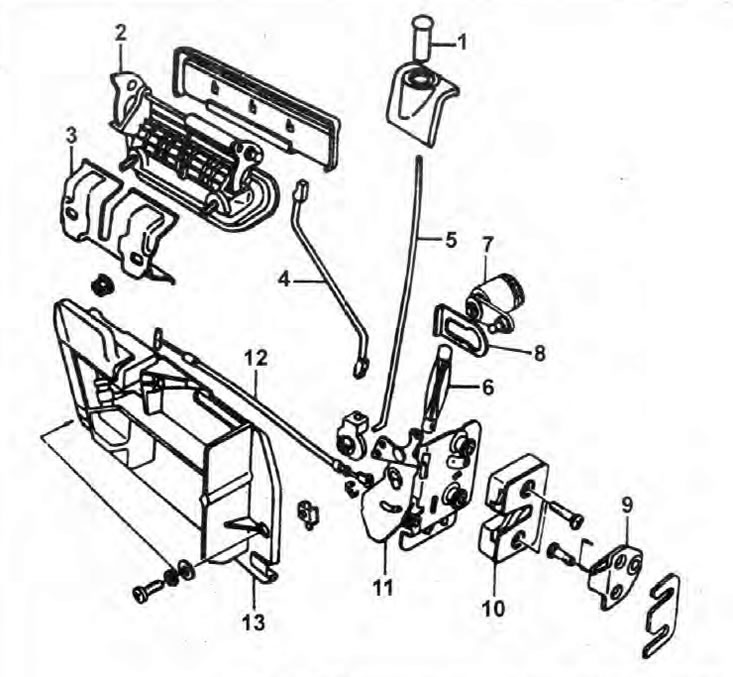
Pic. 11.4. Front door lock and handle components
1. Lock lock button; 2. External handle; 3. External handle lock; 4. Rod connecting the outer handle to the latch control mechanism; 5. Rod connecting the lock button to the latch control mechanism; 6. Rod connecting the lock to the latch control mechanism; 7. Castle; 8. Bracket for fastening the lock to the door; 9. Locking pin plate; 10. Latch; 11. Latch control mechanism; 12. Latch drive cable; 13. Assembling the inner handle of the lock drive.
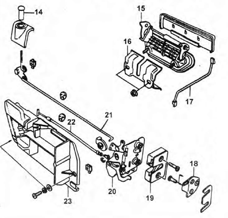
Pic. 11.4. Components for the door lock and handle of the rear side door
14. Lock lock button; 15. External handle; 16. External handle lock; 17. Rod connecting the outer handle to the latch control mechanism; 18. Locking pin plate; 19. Latch; 20. Latch control mechanism; 21. Rod connecting the lock button to the latch control mechanism; 22. Latch drive cable; 23. Assembly of the internal handle of the lock drive.
Removing
Front door lock
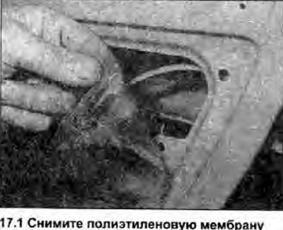
1. Open the door, and fully raise the glass. Remove the inner door lock handle (see below), door trim panel (Chapter 22) and polyethylene membrane (photo). Also remove the plastic shield, if installed.
2. Gently wringing out the spherical joint, disconnect draft of the operating mechanism of the lock.
3. Slide the lock mounting bracket to the door towards the outer handle, then remove the lock.
External handle
4. Open the door, and fully raise the glass. Remove the inner door lock handle (see below), door trim panel (Chapter 22) and a polyethylene membrane.
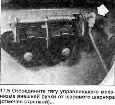
5. Gently depressing the ball joint, disconnect the lock control rod from the outer handle (photo).
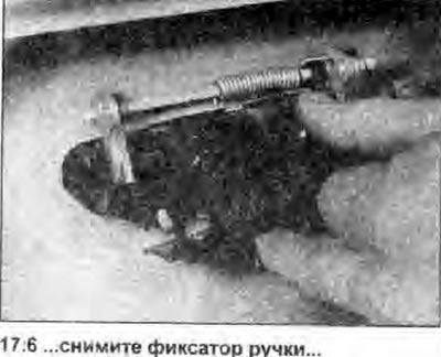
6. Unscrew the two fixing nuts, and remove the handle lock (photo).
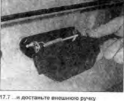
7. From the outside of the door, remove the outer handle (photo). Don't damage the coloring.
Latch and control mechanism
8. Open the door, and fully raise the glass. Remove the inner door lock handle (see below), lock button (see below), door trim panel (Chapter 22) and a polyethylene membrane.
9. Gently depressing the ball joints, disconnect the rod connecting the latch control mechanism to the outer handle, and the rod connecting the latch control mechanism to the lock lock button.
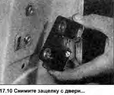
10. Unscrew the two screws, and remove the latch from the door (photo).
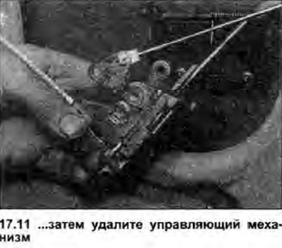
11. Carefully remove the latch control mechanism from inside the door (photo).
Internal lock drive handle
12. Remove door pockets.
13. Carefully separate the armrest from the assembly of the inner handle of the lock drive, unscrew the screws that secure the assembly of the inner handle of the lock drive to the door.
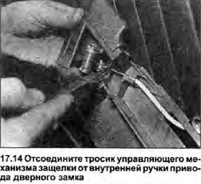
14. Disconnect the latch drive cable from the inside lock drive handle, and thread it through the inside lock drive handle assembly, noting how it runs (photo).
Lock button
15. Unscrew the button from the top of the rod.
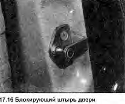
Blocking pin
16. Open the door and mark the installation position of the locking pin with a pencil, then unscrew the two fixing screws (photo), and remove the locking pin.
Installation
Front door lock
17. Install in the reverse order of removal. Make sure the ball joints are securely connected together.
External handle
18. Install in the reverse order of removal. Make sure the ball joints are securely connected together and that the handle on the door is installed without tilting.
Latch
19. Install in the reverse order of removal. Make sure the ball joints are securely connected together.
Internal lock drive handle
20. Install in the reverse order of removal. Make sure the lock cable is properly routed through the handle and is not pinched or twisted.
Lock button
21. Install in the reverse order of removal.
Blocking pin
22. Align the locking pin with the marks made before removal. If installing new components, center the locking pin over the mounting holes, lightly tighten the screws, and check the alignment of the door against the opening in the body (see below). Finally, securely tighten the locking pin fixing screws.
23. The locking pin can only be accurately placed after the door has been correctly positioned in the opening (Chapter 16).
24. Close the door and check that it sits on the seal, without distortion and gaps, and does not protrude relative to the surrounding body elements, and that the door lock closes securely.
25. If you need to correct the setting, open the door and loosen the locking pin fixing screws, then adjust the pin position.
26. When the installation is correct, securely tighten the screws securing the locking pin, and check the operation of the door lock.