



Assembly diagram of the front doors
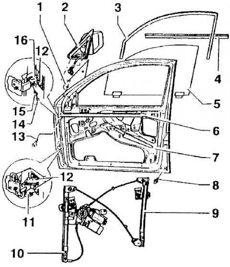
1 – lining; 2 – outside rear view mirror 3 – glass guide seal (pressed into the window frame); 4 – external protective sealing profile of the cavity of the lower part of the door (put on the flange); 5 – glass window door; 6 – internal protective sealing profile of the cavity of the lower part of the door (put on the flange); 7 – door; 8 – limiting bolt (40 Nm); 9 – window lift device; 10 – 10 Nm; 11 – lower door hinge (attached to the door and the A-pillar, together with the travel limiter); 12 – 30 Nm; 13 – screw (mounting screws for outside rear view mirror); 14 – cap; 15 – 20 Nm; 16 – upper door hinge (screwed to the door and pillar A. The hinge pin is inserted into the box-shaped part and locked with pin 15)