



Assembly diagram of the installation of the wheel, shock absorber, propeller shaft and brake
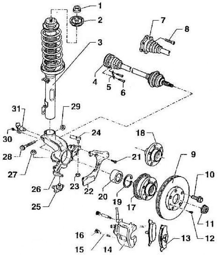
1 – hexagonal flange nut, self-locking, 60 Nm; 2 – stop; 3 – shock absorber strut; 4 – cardan shaft with constant velocity joints; 5 – backing plate; 6 – screw with cylindrical head and internal hexagon in the head, 40 Nm, M8x47; 7 – internal hinge; 8 – screw with cylindrical head and internal hexagon in the head, 40 Nm, M8x18; 9 – brake disc; 10 – wheel mounting bolt, 120 Nm; 11 – twelve-sided nut, self-locking (replace after each assembly); 12 – Phillips head screw, 4 Nm; 13 – brake pads; 14 – disc wheel brake mechanism support (when carrying out work on hanging the front wheel, do not disconnect the brake hose, hang it with a wire or in any other similar way); 15 – guide bolts, 25 Nm; 16 – cap; 17 – wheel hub with rotor of the speed sensor pulse generator (only for vehicles with anti-lock braking system "ABS"); 18 – wheel hub without pulse generator rotor (only for vehicles without ABS); 19 – retaining ring (ensure correct installation); 20 – wheel hub bearing (replace, because during pressing it out it becomes unusable); 21 – Hexagon head screw, 9.5 Nm; 22 – protective sheet; 23 – Hexagonal nut, self-locking, 45 Nm (replace after each assembly); 24 – steering trapezoid rod; 25 – ball joint head (check the rubber seal for damage, replace the ball joint head if necessary); 26 – wheel hub bearing cap; 27 – Hexagonal flange nut, self-locking, 45 Nm (replace after each assembly); 28 – Hex head screw (replace after each assembly); 29 – hexagonal flange nut, self-locking (tighten to 50 Nm and turn another 90°, replace after each assembly); 30 – Allen head screw, 8 Nm; 31 - speed sensor (only for vehicles with anti-blocking device "ABS"; before installing the sensor, lubricate it with a layer of solid plastic grease G 000 650)