
1AV control unit, speed sensor, ignition system, speedometer sensor
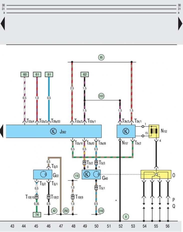
G22 - speedometer;
G40 - Hall speed sensor;
J382 - control unit "1AV";
N152 - ignition coil;
N157 - final output stage;
O - distributor;
Р – tips of a high-voltage wire of ignition;
Q - spark plugs;
T3i - three-pin plug connector, on the speed sensor;
T3j - 3-pin connector, on the speedometer;
T3k - 3-pin plug connector, on the high power output stage;
T10f – 10-pin plug connector, in the cable duct to the left;
T28a - 28-pin plug connector, on the control unit "1AV";
T52a - 52-pin plug connector, on the control unit "1AV";
8 - ground bus between the ignition coil and the engine;
85 - grounding in the motor cable bundle;
110 - grounding in the cable bundle behind the dashboard;
250 - grounding in the connecting beam of the engine;
A2 - connection with a positive pole (15) in a cable bundle behind the dashboard;
D101 - connection with positive pole (15) in the motor cable bundle;
D142 - connection in the connecting bundle of the engine;
* - vehicles with car radio
The structure of circuit diagrams of electrical equipment is located here →
Symbols found in circuit diagrams are here →
Explanations for the symbols found in the wiring diagrams are here →