



Instrument panel, processor, alarms, brake fluid level signal
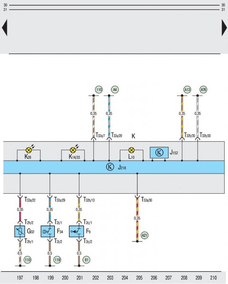
F9 – switch for the parking brake system indicator;
F34 – contact for warning signal in case of emergency drop in brake fluid level;
G32 – coolant level sensor;
J152 – Audible signal for headlights on;
J218 – Instrument cluster processor;
K – instrument panel;
K14/33 – Parking brake system/brake fluid level indicator;
K28 – coolant temperature and level indicator;
L10 – incandescent lamp for instrument panel lighting;
T2c – two-pin plug connector, on the switch for the parking brake indicator;
T2h – two-pin plug connector, on the coolant level sensor;
T2i – two-pin plug connector, on the contact of the warning signal in case of emergency drop in brake fluid level;
T32a – 32-pin plug connector, on the instrument panel (blue);
T32b – 32-pin plug connector, on the instrument panel (green);
81 – ground connection in the wiring harness behind the instrument panel;
110 – ground connection in the wiring harness behind the instrument panel;
119 – ground connection in cable harness, front left;
A4 – connection to positive terminal (58b) in the wiring harness behind the instrument panel;
A13 – connection (door switches for lighting in the body) in the wiring harness behind the instrument panel;
A21 – connection (86s) in the wiring harness behind the instrument panel;
A76 – connection (diagnostic cable K) in the wiring harness behind the instrument panel
View the original on the website SKODABOOK
The structure of the basic diagrams of electrical equipment is located here →
Symbols found in wiring diagrams are here →
Explanations of the symbols found on the electrical diagrams are located here →