



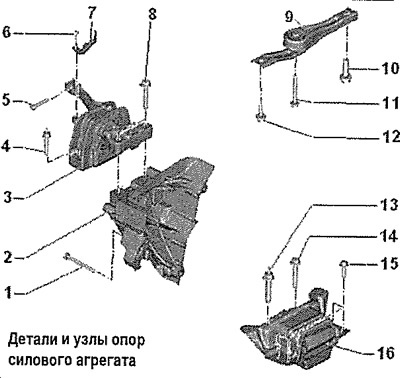
1. 40 Nm and turn 90° (1/4 turn): replace
2. Engine support bracket
3. Engine support: with bracket
4. 40 Nm and turn 90° (1/4 turn): replace
5. 20 Nm and turn 90° (1/4 turn): replace
6.8 Nm
7. Bracket
8. 60 Nm and turn 90° (1/4 turn): replace
9. Lower support of the power unit
10. 130 Nm and turn 90° (1/4 turn): replace
11. 50 Nm and turn 90° (1/4 turn): replace
12. 50 Nm and turn 90° (1/4 turn): replace
13. 60 Nm and turn 90° (1/4 turn): replace
14. 60 Nm and turn 90° (1/4 turn): replace
15. 50 Nm and turn 90° (1/4 turn): replace
16. KP support
Removal and installation the lower support of the power unit
Unscrew bolt "1". Unscrew bolts "2" and "3" and remove the spacer.
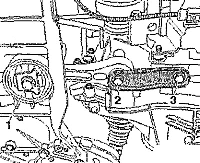
Installation in reverse order.
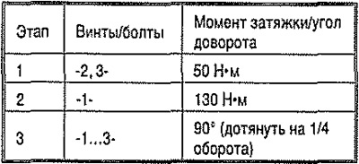
Note: Screws/bolts that are tightened to the specified angle must be replaced.
Tighten the bolts in stages in the specified sequence.
Adjusting the powertrain mounts
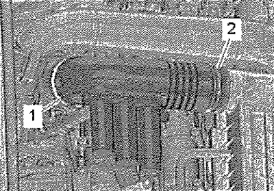
Remove the battery bracket. Loosen clamps "1" and "2" and remove the air pipe. Remove the air filter housing. Remove the windshield wiper arms. Remove the water drainage box casing. Remove the caps of the threaded connections of the front shock absorber strut cups.
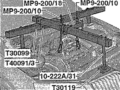
Install the "T30099" crossmember as shown in the figure. Install the carabiners on the engine lugs. Slightly tighten the power unit using the lead screws, but do not lift it.
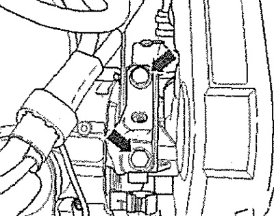
Loosen the engine support "arrow" screws one by one and replace them if this was not done when installing the engine. Tighten the screws.
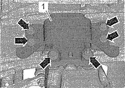
Unscrew the "arrow" screws of the gearbox support "1" one by one and replace them if this was not done when installing the engine. Tighten the screws.
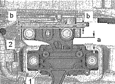
Align the power unit using a crowbar so that the following dimensions are observed: between engine support "2" and engine bracket "1" there must be a distance of "a" = 10 mm. The edge of the cast bracket of engine support "2" must be parallel to console "1". Dimension -b- = dimension -b-.
(The original article is located on SKODABOOK.ru)
Note: The distance "a" = 10 mm can also be checked using, for example, a suitable rod.
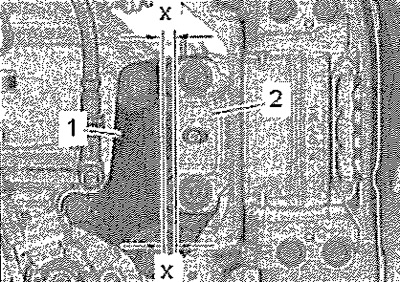
Tighten the support mounting bolts. Ensure that the edges of console "2" and gearbox support "1" are parallel on the gearbox side. Dimension -x- = dimension -x-. Tighten the gearbox support mounting bolts.
Installation in reverse order.