



Contents: Car with air conditioning ⬇ All ⬇ Cars with radiator version 1 ⬇ Cars with cooling radiator versions…⬇ All ⬇ Cars without independent heater ⬇ Car with independent heater ⬇ All ⬇ For vehicles with manual transmission ⬇ For cars with automatic transmission ⬇ All ⬇ For cars with automatic transmission ⬇ All ⬇
Note: The engine is removed downwards together with the gearbox. After installing the engine, all cable ties removed or cut off during dismantling must be reinstalled in their original place. Leave the ignition key in the ignition to prevent the steering column from locking. Risk of injury due to fuel under high pressure. Before opening the high-pressure circuit of the injection system, the fuel pressure must be released to residual pressure.
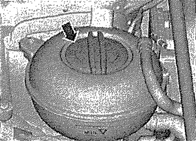
Relieve fuel pressure in the high-pressure circuit. Open the "arrow" cap of the expansion tank.
Warning! Risk of burns from hot steam or hot coolant. When the engine is hot, the coolant in the cooling system is under pressure. To relieve the pressure, cover the expansion tank cap with a rag and carefully unscrew, gradually releasing the pressure.
Engine characteristics
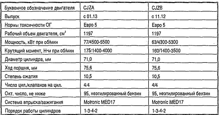
Some points of removal and installation are described in 1.8 and 2.0 l engines.
Remove both front wheels. Remove the noise-insulating casing. Remove both front mudguards. Disconnect the electrical connector "2" on the coolant temperature sensor at the radiator outlet "G83" "3". Drain the coolant.
Caution! Install the used belt only in the previous direction of movement. Incorrect installation may result in belt destruction! Before removing the poly V-belt, mark its direction of movement with chalk or a felt-tip pen.
Car with air conditioning
Caution! Do not open the air conditioning system refrigerant circuit.
Remove the poly V-belt. Disconnect connector "1" from the air conditioning compressor control valve "N₂80". Unscrew the air conditioning compressor "arrow" bolts.
[Material published on the website: SKODABOOK.RU]
Caution! Risk of damage to refrigerant pipes and hoses. Do not stretch, bend or kink refrigerant pipes and hoses.
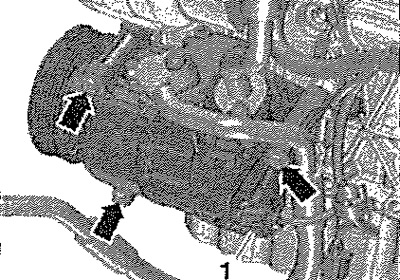
Remove the air conditioning compressor together with the refrigerant hoses, move it to the right and tie it up.
All
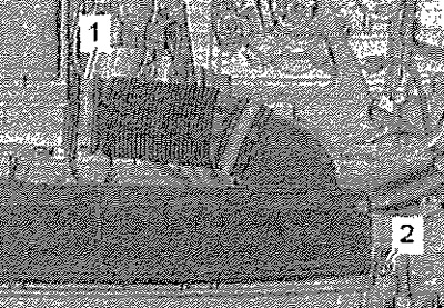
Loosen clamp "1" and remove the air duct. Unscrew screws "2" on the left and right. Unfasten from the front support panel and remove the air duct.
Lift the clamp "arrow" and disconnect the upper left coolant hose from the radiator.
Note: Depending on the vehicle version, 3 radiator versions are installed.
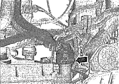
Cars with radiator version 1
Lift the clamp "arrow" and disconnect the right upper hose from the charge air cooling circuit radiator.
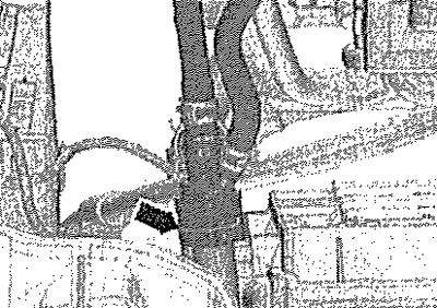
Cars with cooling radiator versions 2 and 3
Lift the mounting bracket "1" and disconnect the coolant hose from the supercharger radiator.
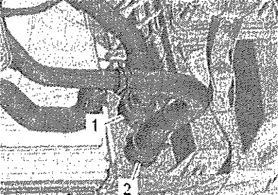
All
After lifting the mounting bracket and loosening the clamp, disconnect both hoses of the "arrow" cooling system.
Disconnect electrical connector "1" by moving the lock back "arrow A" and unlocking it by moving it downwards.
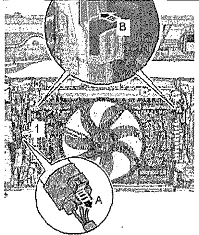
Remove the fan shroud. Disconnect the battery. Remove the battery and its bracket. Unlock the "arrow" lock and disconnect the vacuum hose "1". Release the vacuum hose from the fasteners on the air duct "2".
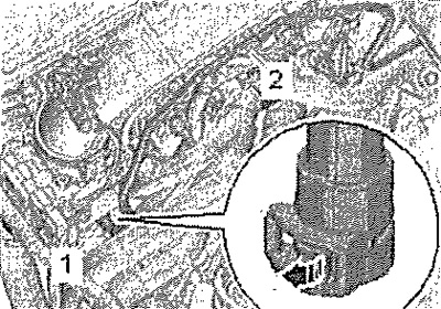
Cars without independent heater
Open the "arrow" clamps and disconnect the coolant hoses from the heater heat exchanger.
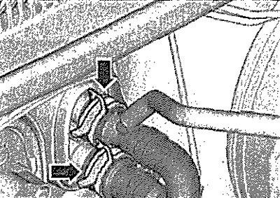
Car with independent heater
After lifting the mounting bracket and loosening the clamp, disconnect both hoses of the "arrow" cooling system.
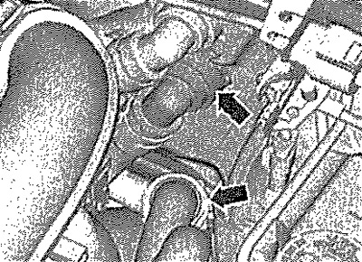
All
Unscrew screw "2" and remove the screw clamp. Unscrew screw "1", unscrew the nut "arrows", tie up the neutralizer.
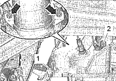
Unscrew the "arrow" screws and remove the bracket.
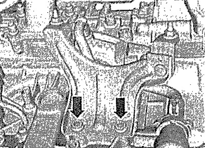
Loosen clamp "1" and disconnect the cooling system hose.
Warning! Risk of injury from fuel. To relieve fuel pressure before opening the fuel system, place a clean rag around the connection and carefully disconnect. Risk of contamination. Observe the rules for maintaining cleanliness when working on the fuel system.
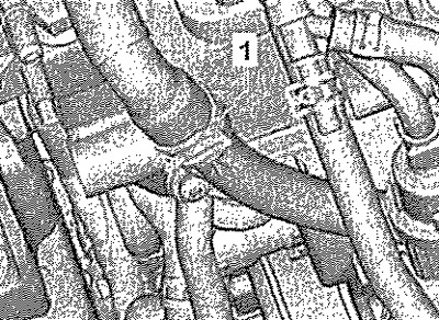
First, press the hose coupling "1" down, then squeeze the clamps "arrows". Remove the hose coupling with the clamps pressed. Press the clamp on the hose "2" going to the adsorber. Disconnect the hose and release it from the fasteners.
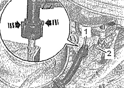
Disconnect the air hose "2". Remove the air filter housing "1" from the support pins by moving it upwards. Loosen the clamps "3" and "4" and remove the air pipe.
Note: For subsequent operations, use the Door Trim Removal Tool -MP8-602/1- to detach the fasteners.
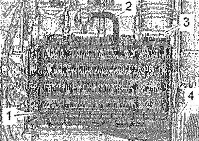
Disconnect the upper connector "1" from the engine control unit "J623".
Note: On vehicles with an engine control unit with a protective cover, the protective cover must first be removed.
Remove connectors "2" and "3" from the bracket and disconnect them. Hang the wires.
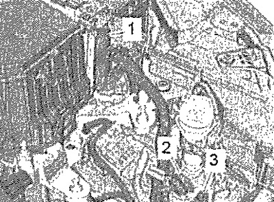
Disconnect connector "2". Unscrew the protection of pole "1" and disconnect the wire from the starter traction relay. Disconnect the ground wire from the body.
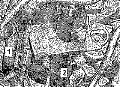
Unlock the "arrow" latches, remove cover "1" of the switching unit in the engine compartment.
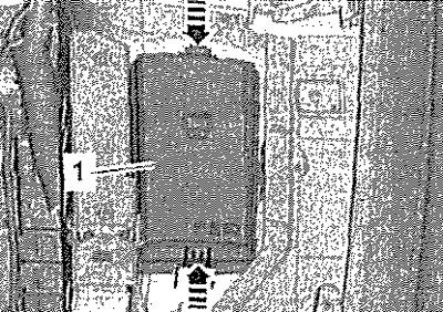
Use a screwdriver to unlock the "arrow" lock, remove cover "1" of the switching unit in the engine compartment by moving it upwards.
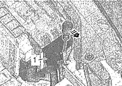
Unscrew the "arrow" nut, disconnect and hang up the leash.
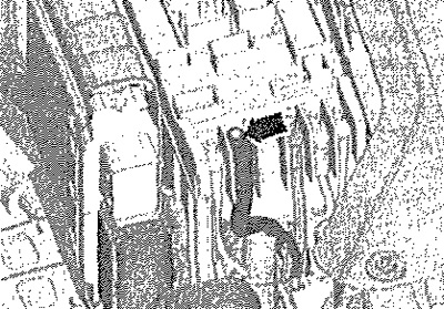
Disconnect connectors "1" and "2".
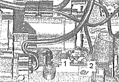
For vehicles with manual transmission
Disconnect the gear shift mechanism from the gearbox. Remove the slave cylinder.
For cars with automatic transmission
Remove the selector cable, disconnect the Mechatronic unit connector and disconnect all brackets from the gearbox.
All
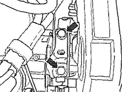
Loosen the engine mount "arrow" screws by approximately 2 turns.
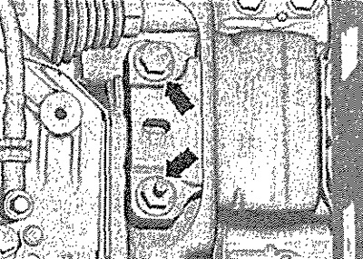
Loosen the gearbox support "arrow" screws by approximately 2 turns.
Disconnect electrical connector "1" from oil level and temperature sensor "G266". Release the wire from the holder "2".
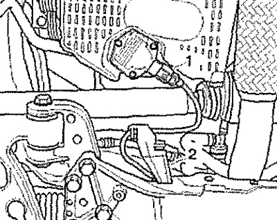
Unscrew the "arrow" nuts of the stabilizer struts on the left and right.
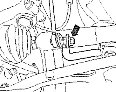
Unscrew screws -1, 2, 3- and remove the lower support of the power unit.
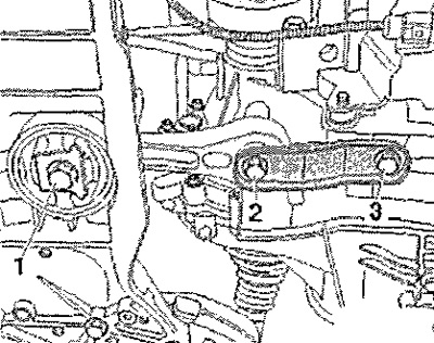
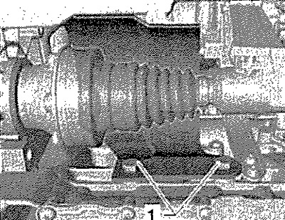
Loosen screws "1" and remove the heat shield of the propeller shaft on the right side, if present.
For cars with automatic transmission
Remove the subframe. Disconnect the left and right drive shafts from the gearbox and tie them up.
Note: Be careful not to damage the protective coating on the drive shaft. For vehicles with manual transmission.
Unscrew the "arrow" nuts of the ball joints on the left and right.
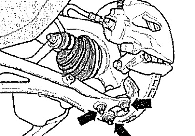
If there is a front left ground clearance sensor "G78", unscrew the nut "arrow" of the left suspension arm. Disconnect the ball joints from the transverse suspension arms on the left and right. Disconnect the left and right drive shafts from the gearbox and tie them up.
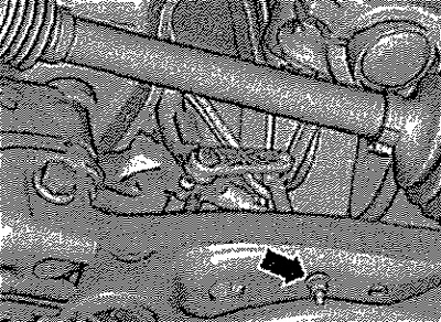
Turn the left shock absorber strut outward and support it with the extension -2024 A/1-, as shown in the figure.
Warning! Risk of injury due to loose support parts. Secure the retainer and ball joint with the stopper "arrow" and nut "1".
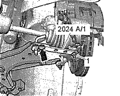
Secure the right ball joint "2" to the suspension arm "1" with the nut "arrow", as shown in the figure.
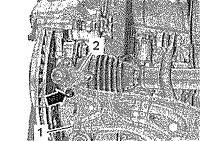
All
Install the T10497/2 adapter on the cylinder block edge as shown in the figure. Position the T10497 engine bracket using the T10497/1 pins on the cylinder block. Secure the T10497/2 adapter with screw "1" on the T10497 engine support bracket and tighten to 20 Nm.
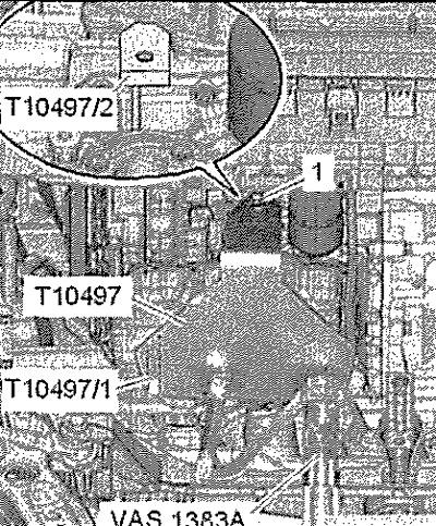
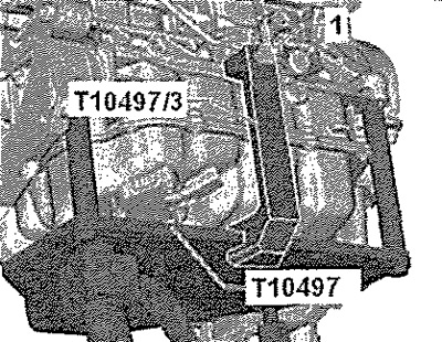
Install the adapter "T10497/3" on the engine bracket "T10497" and tighten bolt "1" to 20 Nm. Secure the jack for engines and transmission units "VAG 1383 A" on the engine bracket T10497 and slightly raise the power unit.
Note: Unscrew the power unit support bolts using a stepladder, such as "VAS 5085".
Completely unscrew the bolts "arrow" of the engine support fastening. Completely unscrew the screws "arrow" of the gearbox support fastening.
Caution! Risk of damage to vacuum lines or electrical wires. Check that all vacuum lines and electrical wires connecting the engine, gearbox, subframe and body are disconnected. When lowering the power unit, remove it from the engine compartment with caution.
Lower the power unit slightly. Then turn the gearbox side of the power unit forward and only then lower it slowly and carefully. Disconnect the gearbox from the engine.