Note.
- Necessary special devices, control and measuring instruments, as well as auxiliary means:
- Fastening clamp "T10038".
- Holder "T10149".
- Device for removing and installing the engine and gearbox, e.g. "VAG 1383/A".
- All screws on chassis parts with rubber-metal supports must always be tightened in the position of the vehicle's unladen weight.
Curb weight
Weight of the vehicle with a full fuel tank, a full windshield washer fluid reservoir, a spare wheel, a tool kit, a jack and without a driver The spare wheel, tool kit and jack must be stored in a place designated for this purpose by the vehicle manufacturer.
Rubber-metal bearings have a limited range of rotation.
Therefore, suspension parts with rubber-metal supports must be brought into a position corresponding to the position occupied during vehicle operation (vehicle curb weight position).
Otherwise, the rubber-metal support is too tight, which would result in a reduction in service life.
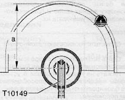
By lifting the suspension arm on one side using a device for removing and installing the engine and gearbox, e.g. "VAG 1383/A" and a mounting bracket "T10149", it is possible to simulate this position on a jack.
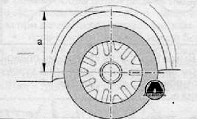
1. Before starting work, measure, for example, with a measuring tape, the dimension "a" from the center of the wheel to the lower edge of the wing.
The measurement must be carried out on the vehicle in the unladen weight position
(Material published on the website: «Skodabook.ru»)
2. Mark the measured value. It will be needed when tightening the bolts or nuts.
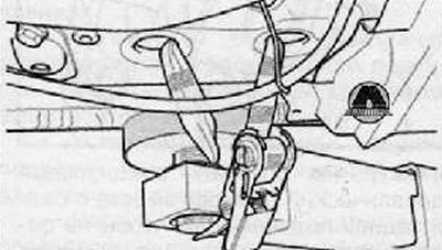
3. Before lifting the suspension arm on one side, it is necessary to tie the car with a mounting clamp (with a tension clamp) "T10038" to the console beam of the device for removal and installation.
Caution: If the vehicle is not secured, there is a risk of it slipping off the cantilever beam of the removal and installation device.
4. Remove the wheel.
5. Turn the wheel hub until one of the holes for the wheel mounting screw is in the upper position.
6. Install the "T10149" mounting bracket using the wheel mounting bolt onto the wheel hub.
7. Raise the wheel bearing housing cover with an engine and gearbox removal and installation device, e.g. "VAG 1383/A", until dimension "a" is reached. Tightening the corresponding bolt or nut is only possible when dimension "a" is reached (value from the center of the wheel to the bottom edge of the wing), which was measured before the start of work.
Attention.
- While the engine and gearbox removal and installation device is located under the vehicle, the vehicle must not be raised or lowered.
- The engine and gearbox removal and installation device, e.g. "VAG 1383/A", should not be left under the vehicle longer than absolutely necessary.
8. Tighten the appropriate nuts and screws to the specified tightening torque.
9. Lower the wheel bearing housing cover.
10. Remove the engine and gearbox removal and installation tool from under the vehicle.
11. Remove the mounting bracket "T10149".
12. Remove the mounting clamp "T10038".