



FWD models (using models from the 22nd week of 2010 as an example)
1. Remove the rear wheels.
2. Remove the rear suspension springs (see Section 12).
3. If there is a suspension height sensor, disconnect its wiring connector (1 in the illustration).
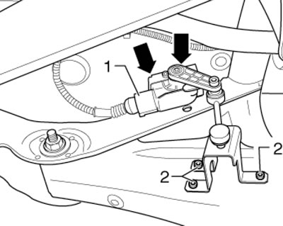
9.3. Connector (1) and fasteners (2) for rear suspension height sensor
4. Remove the lower shock absorber mounting bolt (see illustration).
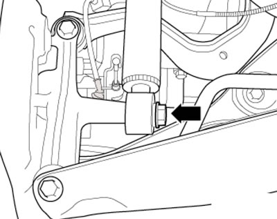
9.4. Lower shock absorber mounting bolt
5. On models with a spring lock (1 in the illustration) parking brake cable, loosen this lock, press the lever (2) in the direction of the arrow and at the same time unhook the cable (3).
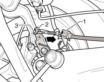
9.5. Disconnecting the cable (with spring lock)
6. On models with a spring bushing (1 in the illustration) parking brake cable, loosen this sleeve on the caliper bracket, press the lever (2) in the direction of the arrow and at the same time unhook the cable (3).
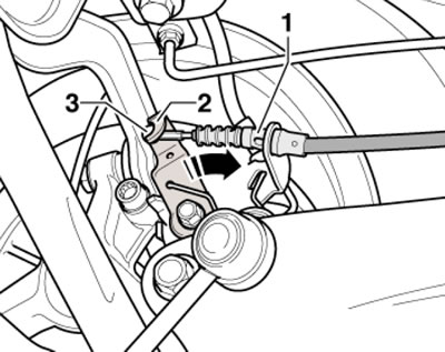
9.6. Disconnecting the cable (with spring bushing)
7. Loosen the parking brake cable bracket mounting bolt on the trailing arm and unhook the ABS wheel sensor cable from the bracket (1 in the illustration) in the places indicated by arrows.
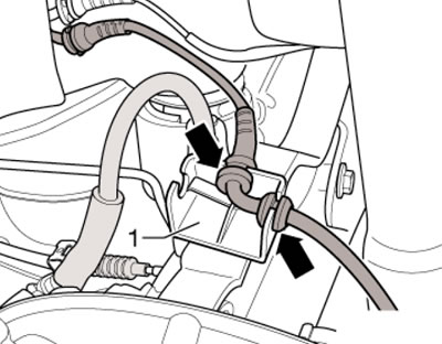
9.7. ABS sensor wire on the bracket
8. On both sides of the vehicle, pull out the locking pin (1 in the illustration) brake line.
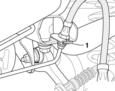
9.8. Brake line retainer
9. Remove the brake calipers without disconnecting the brake fluid hoses from them and hang the calipers on a wire so that the hoses are not stretched (see Chapter 9).
10. Mark the installation position of the bracket relative to the body and unscrew the bolts (arrows in the illustration). Unhook the rear muffler from its mounting on the subframe.
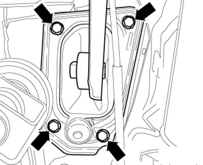
9.10. Bracket bolts
11. Secure the car to the lift legs with T10038 straps (see illustration).
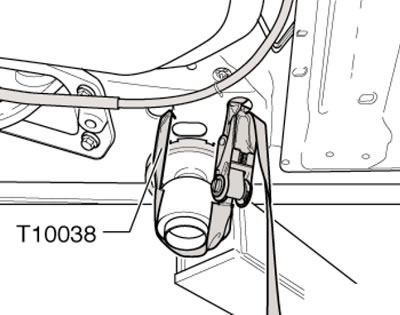
9.11. Securing the vehicle on the lift paw
12. Install the VAG1383/A transmission jack with the VAG1359/2 universal support under the subframe, placing a wooden block between them (see illustration). Secure the subframe to the jack.
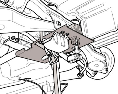
9.12. Installing a jack under the rear subframe
13. Remove the bolts (1 and 2 in the illustration) on both sides.
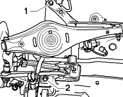
9.13. Subframe mounting bolts
14. Fix the subframe position by screwing in two T10096 centering pins with a force of no more than 20 Nm. Unscrew the two remaining subframe bolts and carefully lower it by about 30 mm, watching the brake lines and wiring.
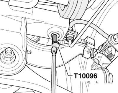
9.14. Fixing the subframe position
15. Release the brake line (1 in the illustration) from the holders (arrows) on the subframe and lower it together with the connected suspension parts.
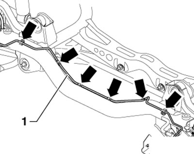
9.15. Brake line attachment points
16. Installation is carried out in reverse order. Finally, carry out a road test (see Chapter 1), check the position of the steering wheel and adjust the rear wheel alignment angles (see Part D).
AWD models
17. Remove the rear wheels.
18. Remove the rear muffler (see Chapter 4).
19. Remove the rear suspension springs (see section 12).
20. Disconnect the electrical wiring connector (2 in illustration 9.3 Chapter 8) haldex clutch control unit between the rear suspension and the body.
21. If there is a suspension height sensor, disconnect its electrical wiring connector (similar to No. 1 in Illustration 9.3).
22. On both sides of the vehicle, disconnect the rear ABS wheel sensor wiring connectors (see Chapter 9) and unhook the ABS wheel sensor cable from the bracket (1 in illustration 9.7) in the places indicated by arrows.
23. Loosen the spring bushing on both sides of the vehicle (1 in the illustration) on the caliper bracket, press the lever (2) in the direction of the arrow and at the same time unhook the cable (3).
24. On both sides of the vehicle, release the parking brake cable from the bracket (3 in illustration 3.23 Chapter 8) on the rear suspension trailing arm and pull the cable out of the bracket.
25. On both sides of the vehicle, remove the lower shock absorber bolt (see illustration 3.19 Chapter 8).
26. On both sides of the vehicle, pull out the locking pin (1 in illustration 9.8) brake line.
27. Remove the brake calipers without disconnecting the brake fluid hoses from them and hang the calipers on a wire so that the hoses are not stretched (see Chapter 9).
28. Mark the installation position of the bracket relative to the body and return the bolts (by analogy with illustration 9.10).
29. Check that there are color marks on the flexible disk of the cardan shaft and on the flange of the Haldex coupling (see illustration 7.11 Chapter 8). Apply these marks if necessary. Remove the bolts securing the propeller shaft to the Haldex coupling flange (see illustration 7.12 Chapter 8).
30. Loosen the two bolts of the middle bearing of the propeller shaft by two turns (see illustration 7.7 Chapter 8) and secure the shaft by placing a wooden block between it and the crossbar of the central tunnel, (see illustration). Pull the driveshaft forward as far as possible.
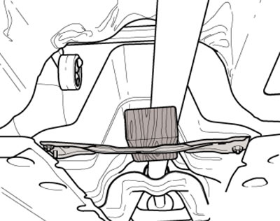
9.30. Block between the cardan shaft and the cross member
31. Secure the car to the lift legs with straps (by analogy with illustration 9.11).
32. Install the VAG1383/A transmission jack with the VAG1359/2 universal support under the subframe, placing a wooden block between them (see illustration 9.12). Secure the subframe to the jack.
33. Remove the bolts (1 and 2 in the illustration) on both sides.
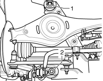
9.33. Subframe mounting bolts
34. Fix the subframe position by alternately screwing in two T10096 centering pins with a force of no more than 20 Nm. Unscrew the two remaining subframe bolts and carefully lower it by approximately 30 mm, monitoring the brake lines and wiring.
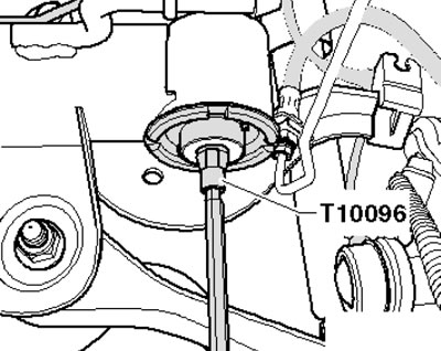
9.34. Fixing the subframe position
35. Release the brake line from the holders on the subframe and lower it together with the connected suspension components.
36. Installation is carried out in reverse order. Finally, carry out a road test (see Chapter 1), check the position of the steering wheel and adjust the rear wheel alignment angles (see Part D).