
Upper wishbone (FWD models)
1. Remove the rear wheel.
2. Remove the rear suspension spring (see Section 12).
3. Unhook the wire from the upper transverse arm (arrow A in Figure 3.29a of Chapter 8) ABS wheel sensor and remove the bolt (1).
4. Mark the position of the eccentric bolt with a marker (see resist. illustration) relative to the subframe, unscrew the bolt and remove the lever.
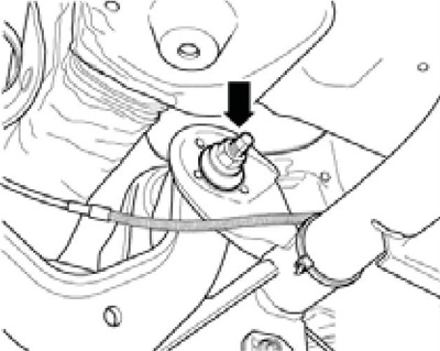
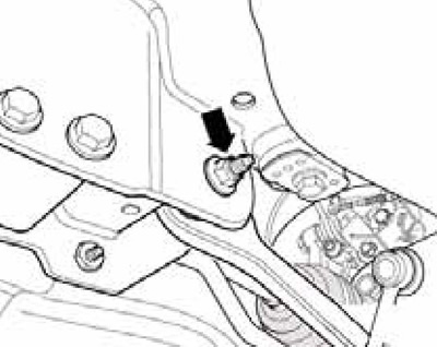
10.4 Nut of the eccentric bolt of the upper control arm on the subframe
5. Install the upper transverse arm and finger-tighten its bolts.
6. Unload the rear suspension (see section 2).
7. Tighten the new eccentric bolt nut to 95 Nm, observing the position of the bolt marked during removal.
8. Tighten the new lever fastener on the hub assembly holder with a force of 130 Nm, and then tighten it through an angle of 90°. Washer (2 in Illustration 3.29a of Chapter 8) between the bolt (1) and the holder of the hub assembly must be installed so that between the washer and the casing (3) there was a gap (IN). Fasten the wire (A).
9. Install spring and wheel. Carry out a road test (see chapter 1).
10. Check rear wheel alignment (see Part D).
Upper wishbone (AWD models)
11. Remove the rear wheel and rear suspension spring (see Section 12).
12. Disconnect the ABS wheel sensor wire from the holder (1 in illustration 9.5) on the upper transverse arm.
13. Turn out a bolt (1 in Figure 3.29b of Chapter 8) fixing the upper arm on the holder of the hub assembly.
14. Mark the position of the eccentric bolt with a marker (see illustration 10.4) relative to the subframe, unscrew the bolt and remove the lever.
15. Establish the top cross-section lever and tighten its bolts by hand.
16. Unload the rear suspension (see section 2).
17. Tighten the new eccentric bolt nut to 95 Nm, observing the position of the bolt marked during removal.
18. Tighten the new lever fastener on the hub assembly holder with a force of 130 Nm, and then tighten it through an angle of 90°. Washer (2 in Figure 3.29b of Chapter 8) between the bolt (1) and the holder of the hub assembly must be installed so that between the washer and the casing (3) there was a gap (IN).
19. Attach wheel sensor wiring, install spring and wheel.
20. Do a road test (see chapter 1), check rear wheel alignment (see Part D).
Lower wishbone
21. Remove the rear wheel, unhook the exhaust system from behind and lower it.
22. Remove the rear suspension spring (see Section 12).
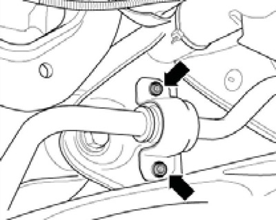
23. Remove the bolt (arrow on resist illustrations) lower wishbone (1).
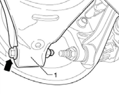
10.23 Lower transverse arm mounting bolt
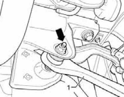
24. If there is a rear suspension height sensor, remove its bolts (1 per resist. illustrations).
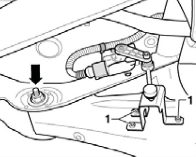
10.24 Lower arm eccentric bolt and suspension height sensor bolts
25. Mark the position of the eccentric bolt with a marker (arrow in illustration 10.24) relative to the subframe, unscrew the eccentric bolt and remove the lever.
26. Install the lower transverse arm and tighten its bolts by hand.
27. Unload the rear suspension (see section 2).
28. Tighten the new eccentric bolt nut to 95 Nm, observing the position of the bolt marked during removal. Install the rear suspension height sensor (in the presence of).
29. Tighten the new lever fastener on the hub assembly holder with a force of 90 Nm, and then tighten it to an angle of 90°
30. Install the rear of the exhaust pipe, spring and wheel.
31. Check rear wheel alignment (see Part D).
Guide lever
32. Remove the rear wheel.
33. Remove the rear suspension spring (see Section 12).
34. Give the nut (1 per resist. illustrations) and separate from the anti-roll bar its rack (2). Remove the bolt (arrow) guide arm (3).
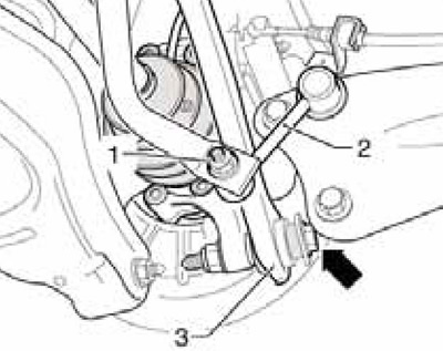
10.34 Stabilizer bar and guide arm (on the example of AWD models; FWD - similar)
35. Align the stabilizer clamp bolts (see resist. illustration).
10.35 Stabilizer clamp bolts
36. Give the nut (arrow on resist illustrations) and remove the bolt towards the rear. Remove the guide lever.
10.36a Guide arm nut (FWD models)
10.36b Guide arm nut (AWD models)
37. There are different options for levers. On the left and right sides, you can install different versions of the levers. Reinforced option levers (2 to resist. illustrations) installed open side back (left and right are different), and ordinary levers (1) - opening down (same on both sides).
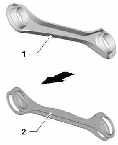
10.37 Guide arm options
38. Install the guide arm and hand-tighten its bolts. Unload the rear suspension (see section 2).
39. Tighten the new stabilizer clamp bolts evenly to the correct torque. Attach the strut to the stabilizer bar.
40. Install the spring.
41. Tighten the new nut (arrow in illustrations 10.36a-b) with a force of 90 Nm, and then tighten it to an angle of 90°.
42. Tighten the new bolt (3 in illustration 10.24) fastening the guide arm to the hub assembly holder with a force of 130 Nm, and then tighten it by an angle of 90°.
42. Install the wheel and do a road test (see chapter 1).
43. Check rear wheel alignment (see Part D).