
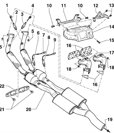
16.1a Details of the receiving part of the exhaust system of models 3.6 l
1 6-pin black connector
2 Pre-catalytic lambda probe "G39" cylinders №№1-3, 50 Nm
3 Precatalytic lambda probe #2 "G108" cylinders №№4-6, 50 Nm
4 6-pin brown connector
5 Nut, 40 Nm, to be replaced
6 Post-catalytic lambda probe #2 "G131" cylinders №№4-6, 50 Nm
7 4-pin brown connector, fixed on the bottom
8 Post-catalytic lambda probe "G130" cylinders №№1-3, 50 Nm
9 4-pin black connector, fixed on the bottom
10, 13, 15 Bolt, 20 Nm
11 Front intake manifold support, on cylinder head
12 Rear intake manifold support
14 Heat shield
16 Gasket, to be replaced
17 Exhaust manifold
18 Nut, replaceable, 25 Nm
19 To the middle and rear of the exhaust system
20 Front of the exhaust system
21 Bolt, 23 Nm
22 Hanger
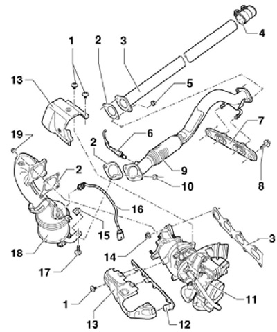
16.1b Details of the receiving part of the exhaust system of models 1.4 l
1 Bolts, 8 Nm
2 Gasket, to be replaced
3 Intermediate pipe
4 Double clamp, 23 Nm
5, 19 Nut, to be replaced, 23 Nm, lubricate the stud with high temperature grease G052 112AZ before screwing
6 Post-catalytic lambda probe "G130", 50 Nm
7 Hanger
8, 17 Bolt, 23 Nm
9 Outlet pipe, do not kink the flexible section more than 10°
10 Nut, replaceable, 23 Nm,
11 Turbocharger assembly with exhaust manifold
12 Bracket
13 Heat shield
14 Nut, to be replaced, 16 Nm, lubricate the stud with high-temperature grease G052 112AZ before screwing on
15 Reinforcing clip
16 Pre-catalytic lambda probe "G39", 50 Nm
18 Catalytic converter with exhaust pipe
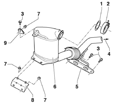
16.1c Installation details of the particulate filter and front exhaust pipe of CLJA diesel models
1 Gasket, to be replaced
2 Clamp, replaceable, 7 Nm
3 Bolt, 25 Nm
4 To the rear muffler
5 Hanger
6 Intake pipe with particulate filter and catalytic converter
7 Nut, 25 Nm
8 Bracket, attached to the cylinder block
9 Bracket, mounted on the cylinder head
Features of installing lambda probes, exhaust gas temperature sensors and particulate filter
2. Before installing the old lambda probe or exhaust gas temperature sensor, high-temperature grease G052 112AZ should be applied to its threads, making sure that it does not get into the openings in the lambda probe housing. The thread of the new lambda probe must be lubricated with assembly grease. Note: After replacing the particulate filter, reset the soot mass using a diagnostic tool.
Removal and installation of a final collector (engine 3.6 l)
3. Remove the upper part of the inlet pipeline (see Section 7).
4. Remove the coolant pipe from the intake pipe support (arrows in Figure 5.8 Chapter 2), remove the bolt (1) and remove the heat shield with the inlet pipe supports.
5. Give nuts of fastening of reception pipes to a final collector (see illustration 5.9 Chapter 2) and move them back slightly.
6. Give nuts of both final collectors (see resist. illustration) and remove them towards the rear.
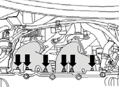
16.6 Fixing the exhaust manifold to the cylinder head
7. Installation is carried out in the reverse order. Use new gaskets and new self-locking nuts.