
Note: If a mechanical failure of the turbocharger is detected, (e.g. damage to compressor blades), in addition to replacing the turbocharger assembly itself, to prevent its subsequent damage, you should make sure that the air supply path is clean and that there are no foreign objects in it. If foreign objects are found in the boost system, clean the boost air lines and replace the intercooler.
Note: The turbocharger can only be removed and replaced complete with exhaust manifold. A description of the removal of the exhaust manifold of the 3.6L engine is given in Section 16.
Petrol models 1.4 l
Note: The check of the vacuum block is carried out by analogy with the check described for gasoline engines 1.8 and 2.0 liters. The end of the adjustment stroke of the rod must be reached at 800 mbar.
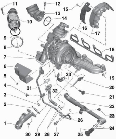
1. Details of the installation of the turbocharger are indicated on Ref. illustrations.
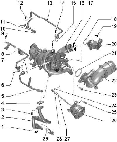
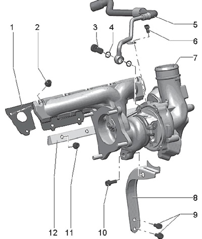
5.1a Turbocharger connections (petrol models 1.4 l)
1, 3, 9 Bolt, 8 Nm
2 Oil return pipe
4, 29 Gasket, to be replaced
5, 8 Coolant pipe
6, 19 Bolt, 11 Nm
7, 11, 15 O-ring, to be replaced
10 Hollow bolt, replaceable, 20 Nm
12, 14 Bolt, 8 Nm
13 Oil supply pipe
16 Turbocharger with exhaust manifold
17, 18, 21 O-ring, to be replaced
20 Valve "N249" exhaust air turbocharger
22 Inlet pipe
23 Bolt, 10 Nm
24 Lock washer, to be replaced
25 Bolt, 20 Nm
26 Vacuum block
27 Locknut, 10 Nm
28 Release handle
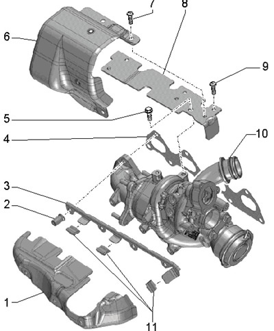
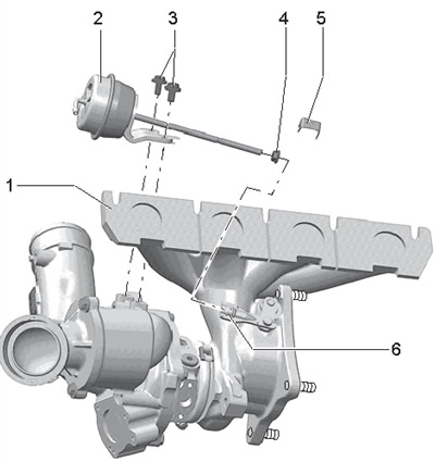
5.1b Turbocharger fittings and fittings (petrol models 1.4 l)
1 Heat shield
2 Nut, replaceable, 16 Nm
3 Shield bracket 1
4 Gasket, to be replaced
5 Bolt, 23 Nm
6 Thermal protection
7, 9 Screen Bolt, 10 Nm
8 Base plate
10 Turbocharger with exhaust manifold
11 Fasteners
2. Remove the inlet connection cap (see illustration 4.3) and it from the air intake. Loosen the clamp and disconnect the air cleaner outlet hose from the turbocharger.
3. Remove the catalytic converter (see Part B).
4. Disconnect the connector (1 per resist. illustrations) sensor "N75" boost pressure adjustment and connector (2) valve "N249" exhaust air from the turbocharger.
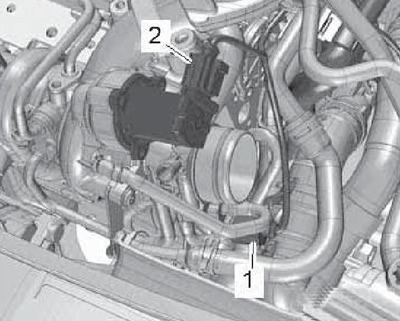
5.4 Sensor connections N75 (1) and N249 (2)
5. Disconnect the connector (2 in Illustration 19.2 of Chapter 2) sensor "G31 " boost pressure with IAT sensor No. 2 "G299", remove the bolts (2) and remove the support bracket (1). Unhook the hoses on the pressure pipe and open the cable duct. Release the latches (arrows), pull the pressure pipe up and out of the turbocharger.
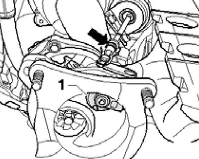
6. Remove the bolt (4 to resist. illustrations) and remove the PCV hose from the turbocharger (arrow).
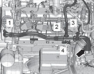
5.6 PCV hose connections
7. Clamp the coolant hoses with tools No. 3094, as indicated on resist. illustrations, unscrew the bolts (1, 3-5), remove the coolant lines from the turbocharger and set them aside.
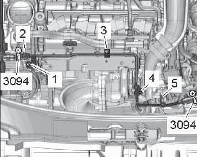
5.7 Removing the coolant hoses
8. Remove the exhaust manifold heat shield (see resist. illustration).
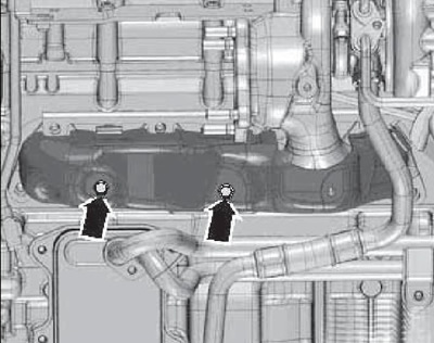
5.8 Fixing the heat shield
9. Turn out bolts (2 and 4 on resist. illustrations) oil supply line, unscrew the hollow bolt (1) and remove the coolant pipe. Remove the bolt (3) and remove the mounting plate.
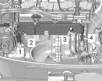
5.9 Removing the mounting plate
10. Turn out bolts (1 and 2 on resist. illustrations) and remove the oil return pipe.
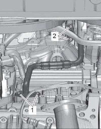
5.10 Fixing the oil return pipe
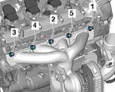
11. Give all the nuts (arrows on resist. illustrations) and remove the bracket from the studs. Remove the exhaust manifold with turbocharger from the cylinder head.
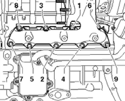
5.11 Turbocharger and exhaust manifold fasteners
12. Installation is carried out in the reverse order. Use new sealing elements. Apply G052 112AZ grease to the studs before tightening the exhaust manifold nuts. Tighten the nuts in the sequence shown in illustration 5.11 with a force of 16 Nm. Before installing the turbocharger, fill the turbocharger with oil through the oil supply connection. After installation, let the engine run at idle speed for about a minute.
Petrol models 1.8 and 2.0 l: removal and installation of a turbocharger
13. Details of the installation of the turbocharger are indicated on Ref. illustrations.
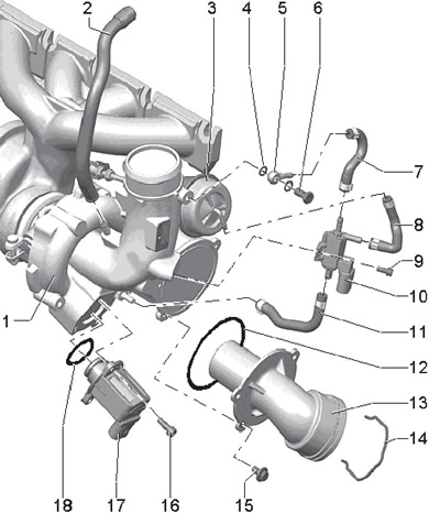
5.13a Hoses and solenoid valves of the turbocharger (petrol models 1.8 l)
1 Turbocharger
2 To intake manifold
3 Turbocharger vacuum unit
4, 12, 18 O-ring, to be replaced
5 Connection
6 Hollow bolt, 8 Nm
7, 8, 11 Hose
9 Bolt, 3 Nm
10 Solenoid valve "N75" boost pressure adjustment
13 Connection
14 Retainer
15 Bolt, 9 Nm
16 Bolt, 7 Nm
17 Valve "N249" exhaust air turbocharger
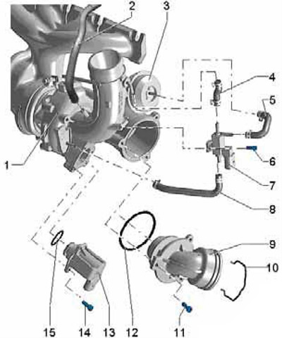
5.13b Turbocharger hoses and solenoid valves (petrol models 2.0 l)
1 Turbocharger
2 To intake manifold
3 Turbocharger vacuum unit
4, 5, 8 Hose
6 Bolt, 3 Nm
7 Solenoid valve "N75" boost pressure adjustment
9 Connection
10 Retainer
11 Bolt, 9 Nm
12, 15 O-ring, to be replaced
13 Valve "N249" exhaust air turbocharger
14 Bolt, 7 Nm
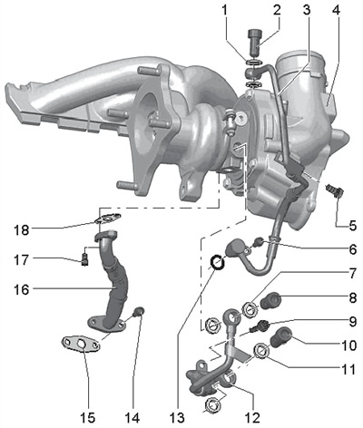
5.13c Turbocharger pipes (petrol models 1.8 and 2.0 l)
1, 7, 11 O-ring, to be replaced
2, 8, 10 Hollow bolt, 20 Nm, then retighten to 45'
3 Oil supply pipe
4 Turbocharger
5, 6, 9 Bolt, 9 Nm
12 Coolant pipe
13 O-ring, to be replaced
14, 17 Bolt, 9 Nm
15, 18 Gasket, to be replaced
16 Oil return pipe
5.13d Fasteners and return pipe for turbocharger coolant (petrol models 1.8 and 2.0 l)
1 Gasket, to be replaced
2 Nut, to be replaced, lubricate the studs with high temperature grease G052 112AZ before tightening
3 Hollow bolt, 20 Nm, then retighten to 45°
4 O-ring, to be replaced
5 Coolant return pipe
6 Bolt, 9 Nm
7 Turbocharger
8 Bracket
9, 10 Bolt, 30 Nm, lubricate the threads with high temperature grease G052 112AZ before tightening
11 Nut, do not loosen when removing the turbocharger, must be replaced, 30 Nm, before tightening, lubricate the studs with high-temperature grease G052 112AZ
12 Fastening strip
5.13e Turbocharger vacuum block (petrol models 1.8 and 2.0 l)
1 Turbocharger
2 Vacuum block
3 Bolt, 10 Nm
4 Nut, 9 Nm, sealed
5 Stop plate
6 Knurled nut
14. Blow the coolant (see chapter 3).
15. Remove the right front wheel arch locker (see chapter 11).
16. On AWD models, remove the right drive shaft heat shield.
17. Remove the intake exhaust pipe (see Part B).
18. Turn out bolts (arrows in Figure 25.4 Chapter 2), raise the latches (1 and 2) and remove the pressure air tube.
19. Disconnect connectors (1 and 2 in Illustration 30.9 of Chapter 2) and release the electrical wiring from the holders (arrows).
20. On models with an additional heater turn out bolts (1 and 2 in Illustration 30.10 Chapter 2) and turn the coolant pipes to the left.
21. Remove the bolts (1 and 2 in Illustration 30.12 of Chapter 2) and remove the turbocharger bracket.
22. Remove the hollow bolt (2 in Illustration 30.13 of Chapter 2) and set the coolant line aside. Remove the oil return line bolts on the cylinder block and the bolt (3) oil supply line.
Note: For clarity, the illustration shows the removed engine.
23. Remove the PCV tube (1 in Illustration 23.2 of Chapter 2), remove the bolts (arrows) and remove the intake manifold by loosening the clamp (2). Seal the turbocharger connection to keep dirt out.
24. Disconnect the connectors of the ignition coils (see Section 14 Chapter 1) and set the wiring aside.
25. Disconnect the coolant line going to the expansion tank (see illustration 30.16 of Chapter 2).
26. Disconnect the vacuum line (1 in Illustration 30.52 of Chapter 2) at the connection point (2) and release it from the holders. Disconnect the coolant hoses from the coolant pipe (arrows), disconnect the ground wire (3) and remove the bolt (4).
27. Remove the bolts (1-3 in Figure 30.19 of Chapter 2) and remove the heat shield along with the coolant pipe.
28. Disconnect the coolant hose (see Figure 30.20 of Chapter 2) and release it from the holder.
29. Give nuts (see resist. illustration) and remove the turbocharger and exhaust manifold assembly upwards.
5.29 Turbocharger assembly fastening nuts
30. Installation is carried out in the reverse order. Use new sealing elements and self-locking nuts. Tighten the turbocharger assembly fastening nuts in sequence (1-5 in illustration 5.29) in 4 stages: 5 Nm, 12 Nm, 16 Nm, 25 Nm. Before connecting the oil supply pipe, fill the turbocharger with engine oil through the port for connecting this pipe. The coolant return line is installed together with the turbocharger. After starting the engine for the first time, let it run for about a minute at idle speed.
Gasoline engines 1.8 and 2.0 l: checking and replacing the vacuum block
31. Make sure that the hoses of the turbocharger and the valve solenoid "N75" boost pressure control, are not clogged or leaking, and the valve "N75" serviceable. The engine must be warmed up to a temperature of at least 60°C.
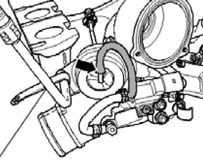
32. Start the engine and watch the traction (And on the opposite illustrations) vacuum block using a mirror. Ask an assistant to increase the engine speed by sharply pressing the gas pedal - the thrust should shift.
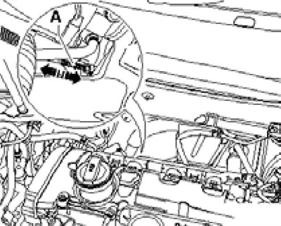
5.32 Vacuum block pull
33. If the rod does not move when the rpm is increased, connect the VAS6213 hand vacuum pump to the vacuum unit as indicated on the reference. illustrations. Move the sliding ring at the vacuum pump fitting towards the pressure gauge.
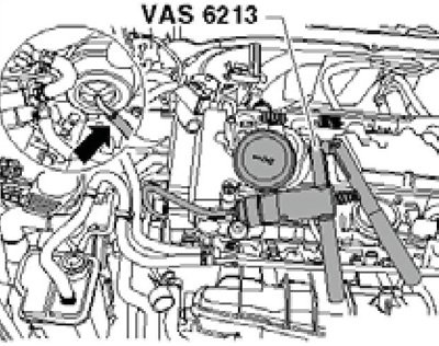
5.33 Vacuum unit hose
34. When working with a vacuum pump, look at the draft (And in illustration 6.32) vacuum block: at a pressure of approx. 300 mbar, the rod should begin to move, and at approx (10 mm). Caution: Do not pressurize more than 750 mbar to avoid damaging the vacuum block. If the pressure is not reached and drops suddenly, replace the vacuum block as described below. If pressure builds up but the link does not move, check the wastegate lever for smooth operation: if the lever is blocked or sticky, the vacuum unit should also be replaced.
35. Remove the turbocharger (see subsection above).
36. Remove the lock washer above the rod on the turbocharger (1 per resist. illustrations).
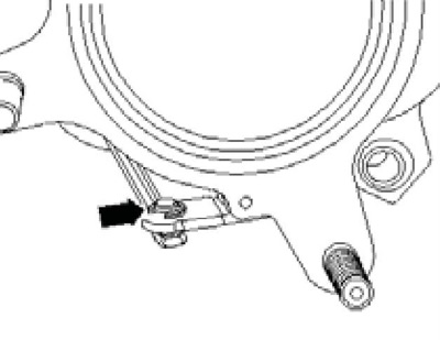
5.36 Thrust lock washer
37. Loosen locknut (2 to resist. illustrations), separate the link from the turbocharger (3), remove the bolts (arrows) and remove the vacuum block (1).
5.37 Fixing the vacuum unit
38. Installation is carried out in the reverse order. After disconnecting the rod, the vacuum unit should be adjusted.
Petrol engines 1.8 and 2.0 l: adjustment of the vacuum unit
Note: Adjustment of the vacuum block is required only after disconnecting its rod and is carried out with the turbocharger removed.
39. Remove the turbocharger (see subsection above).
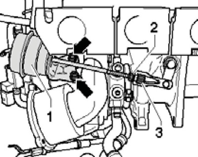
40. Disconnect the hose from the vacuum unit (see resist. illustration).
5.40 Hose connection on the vacuum unit
41. Remove the lock washer above the rod on the turbocharger (1 in illustration 5.36) and loosen the locknut (2 in Figure 5.37).
42. Preinstall wastegate (1 per resist. illustrations) above the vacuum block (arrow) so that the damper can still be turned manually.
5.42 Preset wastegate
43. Assemble the vacuum pump VAS6213, the tester VAG1397A and the pressure control valve VAS6342 as indicated on the resist. illustrations. Connect the valve VAS6342 to the lever (1). Move the sliding ring at the vacuum pump fitting towards the pressure gauge. Turn on the VAG1397A tester and turn its switch to the position "II".
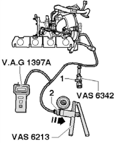
5.43 Control devices
44. Attach the MPZ-447 holder to the turbocharger (arrow on resist illustrations). Attach indicator VAS6341/1 with 30 mm extension VAS6341/3 and flat nut AVS6341/4 to the holder. At zero pressure, set the preload indicator to 1 mm, and then reset it to zero. Check the smoothness of its movement of the indicator.
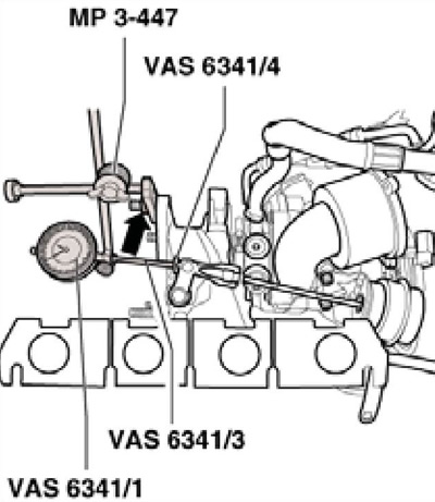
5.44 Setting the indicator
45. Working with a vacuum pump, create a pressure of 460±5 mbar (according to the tester VAG 1397). The indicator should show 4.1-4.3 mm. Otherwise turn the vacuum block rod until this dimension is reached.
46. Finger tighten the locknut and repeat the measurement. Relieve the pressure via the control valve to 0 bar and reset the indicator.
47. Working with a vacuum pump, again create a pressure of 460±5 mbar (according to the tester VAG 1397) and record the indicator reading (this will count as value #1). Then, increase the pressure to 650-700 mbar and drop it to 460±5 mbar. Record the indicator reading again (this will count as value #2). Add values #1 and #2 and then divide them by 2. The result should be 5±0.25 mm.
Otherwise, adjust the position of the rod, finger-tighten the locknut and repeat the adjustment.
48. When the value specified in paragraph 47 is reached, tighten the locknut to 9 Nm and fix with paint. Install the lock washer over the vacuum block rod.
Diesel engines 2.0 l (CFFB, CFGB and CLJA)
49. Details of the installation of a turbocharger are indicated on Ref. illustrations.
5.49 Turbocharger installation details (diesel engines 2.0 l CFFB, CFGB, CLJA)
1 Connecting pipe, to EGR radiator
2, 18, 31 Gasket, to be replaced
3 Bolt, 20 Nm, to be replaced
4 Bolt on bracket 33, 10 Nm
5, 15 Bolt, 15 Nm
6, 17 Thermal shield
7 Turbocharger
8 Retaining ring
9, 14 O-ring, to be replaced
10 Pulsation damper
11, 12 Bolt, 9 Nm
13 Inlet connection
16 Wiring bracket
19 Nut, replaceable, 24 Nm
20 Sensor #1 "G235" flue gas temperature (upstream sensor "G507" turbocharger temperature), 45 Nm
21 Bolt, 20 Nm
22 Turbocharger support, for oil return line
23 Bolt, 10 Nm
24, 28 O-rings of different diameters, must be replaced
25 Hollow bolt, 60 Nm, to be replaced
26, 29 Oil supply line, union nuts tighten to 22 Nm
27 Hollow bolt, 30 Nm, to be replaced
30 Nut, 24 Nm
32 Oil return line
33 Oil supply bracket