
Fuel delivery module and sensor "G" fuel reserve
1. Make sure the tank is no more than 1/4 full. Remove fuel if necessary (see Section 3).
2. Turn off the ignition and electrical appliances, remove the key from the ignition switch.
3. Remove the back seat (see chapter 11).
4. Unhook the cover (4 in illustration 3.18) with block "J538" (1) fuel pump control. On models with an additional heater, additionally disconnect the 2-pin connector of the metering pump "V54".
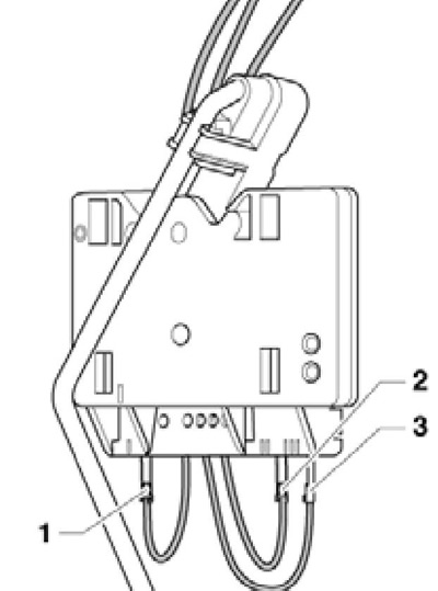
5. Disconnect the 5-pin connector (1 in illustration 3.19), disconnect the black supply line (2) and blue return line (3) pushing on their retaining rings. On models with an additional heater, further extend the suction line of the metering pump "V54", by loosening the bottom clamp.
6. Give the retaining ring of the fuel supply module with the key T30101 (see resist. illustration).
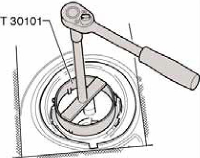
12.6 Loosening the circlip
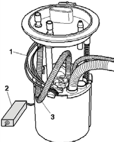
7. Slightly lift the closing flange and make sure that its spring (2 in illustration 12.7a) still attached to the flange (1). If the spring (2) loose on guide tube (3), when removing the flange, hold it with your fingers. Remove the fuel delivery module flange and o-ring from the fuel tank and lay the delivery module aside with the lines connected. Remove the jet pump, separate the fuel line through the opening in the tank (1 in illustration 12.7b), to the jet pump and disconnect the fuel supply line from the fuel delivery module (2).
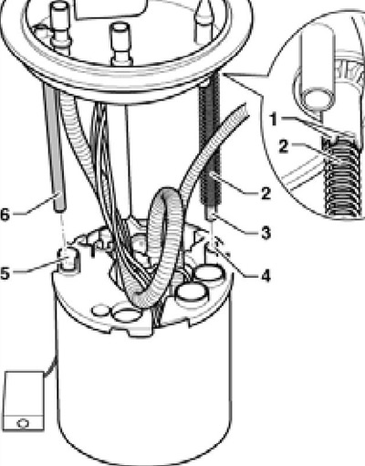
12.7a Details of the fuel supply module
12.7b Removing the fuel delivery module
8. Remove the fuel delivery module from the tank being careful not to damage the wiring or bend the sensor float "G" fuel reserve. Pour fuel out of the module. If necessary, use a screwdriver to pry out the fasteners (see illustration 12.8a), pull out the sensor "G" up and disconnect its connectors (see illustration 12.8b): (1) − brown, (2) - blue, (3) - black.
12.8a Sensor G clamps
12.8b Sensor connectors
9. Install a new dry o-ring in the tank opening and lubricate it with fuel only from the inside to install the closing flange. If removed, connect and install sensor "G". Insert the fuel delivery module into the tank in such a way that the sensor float is not bent "G".
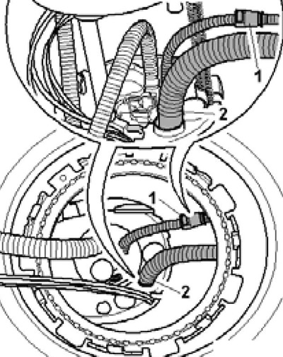
10. Install jet pump and connect fuel lines. Make sure the spring (2 in illustration 12.7a) held by paws (1) flange. Insert guide tube first (3) into the hole (4) a, then lower the flange until the guide tube is fixed (6) in the hole (5). Make sure the wires (1 per resist. illustrations) and fuel supply line (3) routed as shown, and the float arm (2) not blocked.
12.10 Wiring and hose diagram (until 06.2010)
11. The mark on the flange must be opposite the mark on the tank (see resist. illustration).
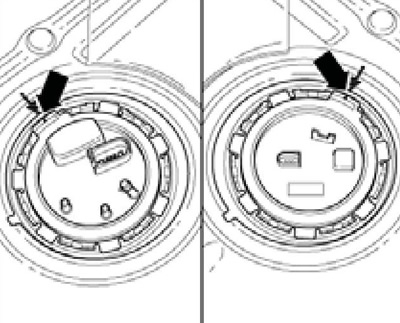
12.11 Installation position of the fuel delivery unit (left) and sensor G169 (on right)
Note: The mark on the tank may be difficult to see due to the flooring.
Press on the closing flange, tighten the circlip to 110 Nm and connect the fuel lines. Plug in the electrical connector.
12. Close the cover with the block "J538" so that the arrow on it is facing forward.
Jet pump and sensor #2 "G169" fuel reserve
Note: The suction pump should only be checked if the engine stalls due to lack of fuel and the fuel gauge needle is at ¼.
13. Make sure the tank is no more than ½ full. Remove fuel if necessary (see Section 3).
14. Turn off the ignition and electrical appliances, remove the key from the ignition.
15. Remove the back seat (see chapter 11).
16. Give a lock ring a key Т30101, by analogy with an illustration 12.6.
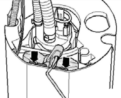
17. Gently pull out the sensor "G169" out of the tank, press the latches (see resist. illustration) and disconnect the jet pump. Remove the sealing ring.
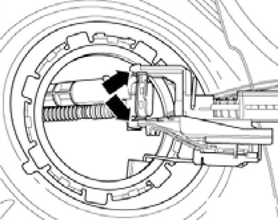
12.17 Separation of the G169 sensor from the jet pump
18. To remove the suction pump, additionally remove the fuel supply module (see subsection above) and pull the suction pump through the sensor opening "G169". Check that the fuel lines are securely connected to the suction pump, that they are intact and that the pump is clean. Install suction pump.
19. Install a new dry sealing ring in the tank opening and only now lubricate it with fuel from the inside.
20. Install the G169 sensor in accordance with illustration 12.11 and tighten the retaining ring with a force of 110 Nm.
21. Further installation is carried out in reverse order.