
Note: When working on fuel system components, observe the precautions given in Chapter 1.
Throttle body
Removing
1. Guided Chapter 2, remove the air filter cover.
2. Guided Chapter 9, depressurize the fuel system, then connect the negative battery cable.
3. Disconnect the fuel hoses of the channels on the side of the throttle body. Arrows indicate direction of fuel flow (Are there marks on the hoses?) (see illustrations).
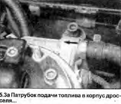 | 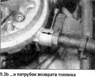 |
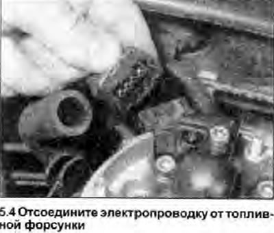
4. Disconnect the wiring harnesses from the connector on the throttle body, mark them so as not to be mixed up during installation (see illustration).
5. Guided Chapter 4, disconnect the throttle cable from the throttle body.
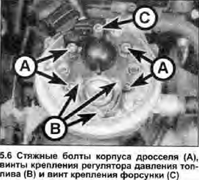
6. Loosen and remove the four pinch bolts securing the throttle body to the intake manifold (see illustration). Lift the throttle body, remove the gasket (where available). Unless necessary, it is not recommended to separate the upper and lower halves of the throttle body - they are fastened with two internal tie bolts. If separated, use a new gasket when reassembling.
Installation
7. Installation is carried out in the reverse order; replace all gaskets. Tighten the tie bolts. Finally, check and, if necessary, adjust the throttle cable.
Fuel burner
Removing
8. Guided Chapter 2, remove the air filter cover.
9. Guided Chapter 9, depressurize the fuel system, then disconnect the negative battery cable.
10. Disconnect the wiring harnesses from the connector on the injector, mark them so as not to be mixed up during installation.
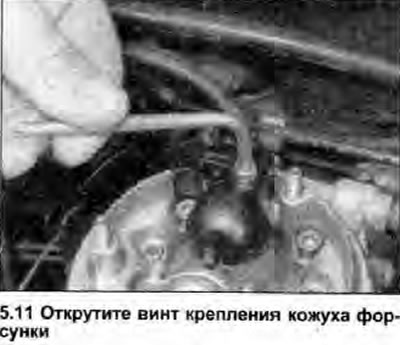
11. Loosen the screw and lift the injector/inlet air temperature sensor shroud (see illustration). Remove the pad.
12. Release the fixing washer, then remove the nozzle from the throttle body, removing the O-ring (see illustration).
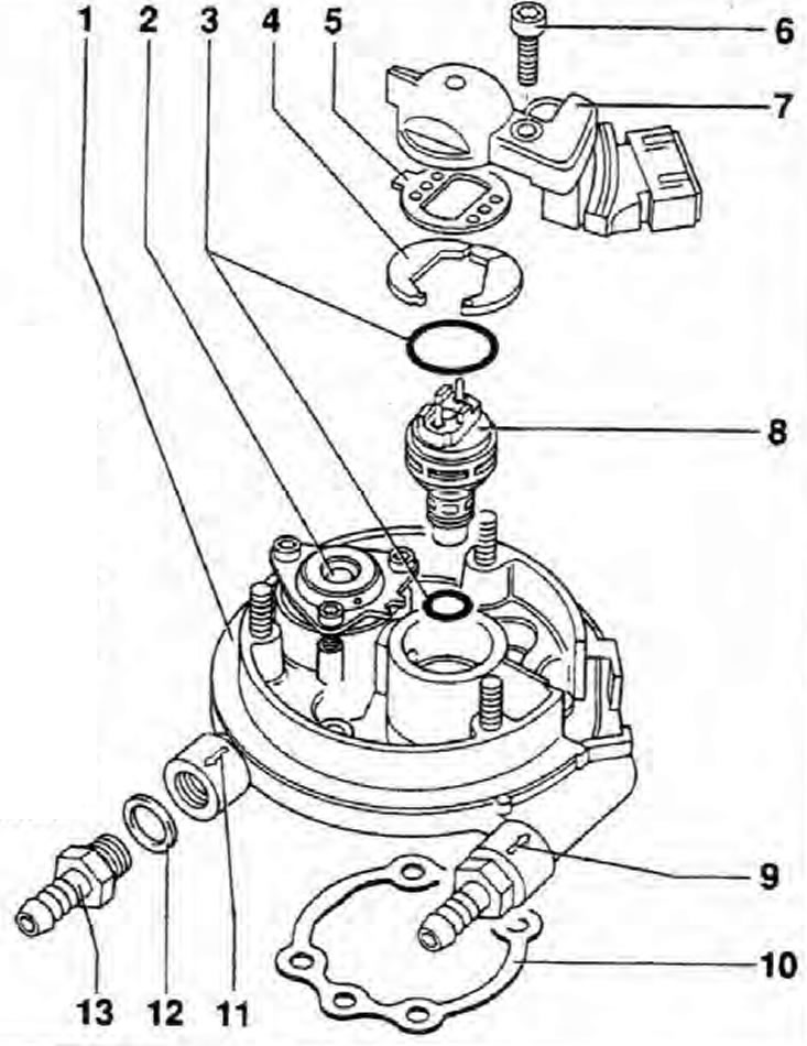
5.12. Top half of throttle body, showing injector fasteners
1. Upper part of the throttle body; 2. Fuel pressure regulator; 3. O-ring; 4. Mounting washer; 5. Gasket; 6. Screw for fastening the nozzle / inlet air temperature sensor; 7. Inlet air temperature sensor; 8. Fuel injector; 9. Fuel supply pipe; 10. Gasket between the upper and lower parts of the throttle body; 11. Fuel return pipe; 12. Seal.
13. Using a multimeter, check the electrical resistance of the injector, and compare the result with the data in Specifications.
Installation
14. Installation is carried out in the reverse order of removal. Replace all O-rings and gaskets. Apply a suitable sealant to the screw threads, then insert and tighten the fastening screw with a tightening torque specified specifications.
Inlet air temperature sensor
15. The inlet air temperature sensor is an integral part of the nozzle mounting cover. Its removal is described in the previous subchapter.
Fuel pressure control
Removing
16. If checking the operation of the fuel pressure regulator, disassemble the unit as described below and check that the internal components are clean and undamaged.
Note: The fuel pressure regulator components are factory fitted to the top of the throttle body. If the pressure regulator is faulty. the company recommends replacing the upper part of the throttle body. Please consult your spare parts supplier.
17. Remove the air filter cover, following Chapter 2.
18. Guided Chapter 9, depressurize the fuel system, then disconnect the negative battery cable.
19. Referring to the relevant subchapter, unscrew the screw and lift the intake air temperature sensor/nozzle cover.
20. Loosen and remove the three mounting screws, lift the fuel pressure regulator mounting frame.
21. Lift the top cover, spring and diaphragm.
22. Thoroughly clean all components, then inspect the diaphragm for cracks or other damage.
Installation
23. Install pressure regulator in reverse order of removal.
Throttle position block
Removing
24. Disconnect the negative battery cable. Remove the air filter cover, following Chapter 2.
25. Guided Chapter 4, disconnect the throttle cable from the throttle body.
26. Disconnect the wiring connector from the throttle position unit.
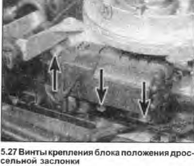
27. Unscrew the fastening screws (see illustration), and remove the block (together with the throttle cable mounting bracket) from the throttle body.
Installation
28. Installation is carried out in the reverse order. Note that if a new unit has been installed, the idle switch adjustment will need to be checked - consult your dealer as this work requires access to test equipment.
Throttle Potentiometer
29. Guided by the relevant subchapter, remove the throttle body. The throttle potentiometer is built into the bottom of the throttle body and cannot be replaced separately.
Idle switch
30. Guided by the relevant subchapter, remove the throttle position unit. The idle switch is built into this unit and cannot be replaced separately.
31. If a new throttle position unit has been installed, the idle switch adjustment needs to be checked - consult your dealer as access to testing equipment is required to perform this work.
Lambda sensor
Removing
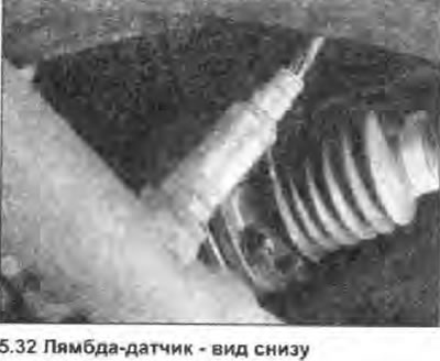
32. Lambda sensor screwed into the exhaust pipe, in front of the catalytic converter (see illustration).
33. Disconnect the negative battery cable. Disconnect the wiring harness from the connector located in the holder on the transmission.
34. Working under the vehicle, loosen and remove the sensor. Be careful not to damage its tip.
Installation
35. Apply some anti-blocking material to the sensor threads.
36. Install the sensor on the casing, clamp it with the correct tightening torque. Repair wiring harness connection. Please note that the type of Lambda sensor installed depends on the specification of the vehicle - the sensors are not interchangeable and cannot be used from another model.
Coolant temperature sensor
Removing
37. The coolant temperature sensor of the control system is screwed into the intake manifold (do not confuse it with a temperature gauge sensor). If the sensor fails, the engine runs unstable during warm-up.
38. The resistance of a hot sensor should be about 2 kOhm, and a cold one - about 300 Ohm.
39. To replace the sensor, disconnect one of the hoses and drain the coolant from the manifold. Plug the hole in the manifold.
40. Disconnect the electrical wiring and unscrew the sensor.
Installation
41. Screw the sensor into place using a new gasket.
42. Connect electrical wiring and add coolant.
Electronic control device (ECU)
43. The ECU is installed in the left side of the engine compartment. The unit is coded and must not be removed without consulting the dealer, otherwise it may not function correctly after reconnecting the multi-pin plug.
Fuel pump relay and fuse
44. The relay and fuse of the pump are mounted in a block that is located in the passenger compartment.
45. The relay is in position 5 on the relay board and is powered by fuse 4.
46. Remove the relay from the socket, remembering its location.
47. Please note that when the fuse is removed in the engine control system, the accumulated information is lost (like disconnecting the battery). For «learning» system before driving, you need to let the engine idle for several minutes.