



Note: To remove the bracket, remove the drive belt, alternator (see Chapter 5), compressor (see Chapter 3) and unscrew the bracket bolts.
1. Details of the auxiliary drive installation are shown in the accompanying illustration.
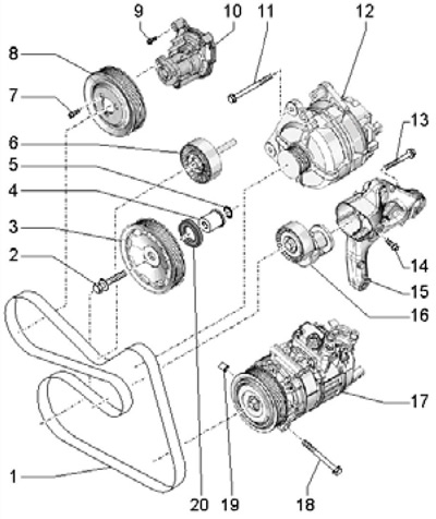
16.1 Auxiliary drive components
1 Drive belt
2 Pulley bolt 3, must be replaced, 150 Nm, then tighten to an angle of 180°, when tightening, the thread must be lubricated, but the supporting surface must not
3 Crankshaft pulley, bearing surfaces must not be lubricated
4 Bushing, bearing surfaces must not be lubricated
5 Sealing ring, subject to replacement
6 Intermediate roller, 40 Nm
7 Pulley bolt 8, 20 Nm
8 Water pump pulley
9 Bolt, 9 Nm
10 Water pump
11 Bolt, 25 Nm
12 Generator
13 Bolt, to be replaced, 40 Nm, then tighten to an angle of 90°
14 Bolt, 25 Nm
15 Auxiliary units bracket (tensioner and compressor)
16 Belt tensioner 1
17 Air conditioning compressor
18 Bolt, 25 Nm
19 Centering sleeve
20 Front crankshaft oil seal
2. Remove the sound insulation under the engine compartment and the right front wheel arch liner (see Chapter 11).
3. If the belt being removed is intended to be reused, mark the direction of its movement on it.
4. To loosen the belt tension, pull the tensioner in the direction of the arrow (see accompanying illustration) with a 16 mm open-end wrench, and then secure the tensioner with a 4 mm Allen key or T10060A pin.
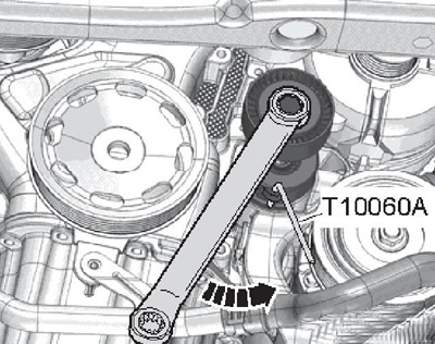
16.4 Fixing the drive belt tensioner
5. Remove the accessory drive belt from the pulleys and rollers.
6. Installation is carried out in the reverse order. If a used belt is installed, the marks on it must face the direction of its movement when the engine is running. The belt should be laid starting from the crankshaft pulley and finishing on the tensioner roller. Make sure that the belt is correctly seated on the pulleys. The belt routing diagram is shown in the accompanying illustration.
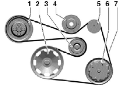
16.6 Drive Belt Routing Diagram
1 Water pump pulley
2 Crankshaft pulley
3 Tensioner roller
4 Intermediate roller
5 Generator pulley
6 Compressor pulley
7 Drive belt