



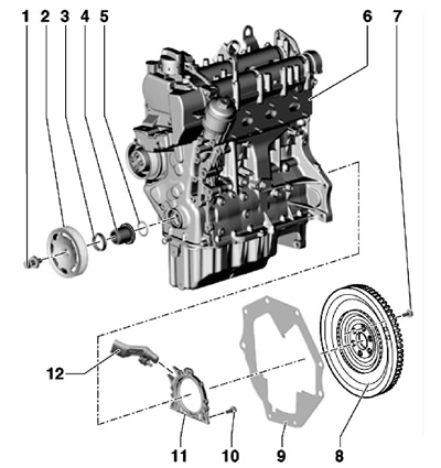
18.1 Crankshaft oil seal installation details
1 Pulley bolt 2, must be replaced, when tightening the thread must be lubricated, but the contact surface must not; 150 Nm, then tighten to an angle of 180°
2 Crankshaft pulley, contact surface should not be lubricated
3 Front crankshaft oil seal
4 Bearing bushing, contact surface should not be lubricated
5 Sealing ring in the bushing, subject to replacement
6 Engine
7 Bolt, to be replaced, 60 Nm, then tighten to an angle of 90°
8 Flywheel
9 The intermediate plate must fit onto the guide bushings and must not be bent or damaged
10 Bolt, subject to replacement, 10 Nm
11 Sealing flange with CKP sensor rotor and rear crankshaft oil seal
12 SKR sensor "G28", secured with a bolt with a force of 5 Nm
Front oil seal
2. Remove the accessory drive belt (see Section 6).
3. Turn the crankshaft clockwise to the TDC position of piston No.1 (see Section 19).
4. Remove the crankshaft pulley (see Section 17).
5. Unscrew the inner part of the MP1-226 puller by 3 turns (approximately 5 mm) from the outer part and fix it in this position with a knurled screw. Lubricate the threaded head of the puller, place it in place and, applying strong pressure, screw it into the seal as far as possible. Loosen the knurled screw and turn the inner part of the puller against the crankshaft to remove the seal (see accompanying illustration).
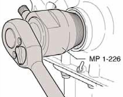
18.5 Front Oil Seal Removal Tool
6. Remove the bearing sleeve from the crankshaft journal and clean the mating surfaces of the crankshaft sprocket and the bearing sleeve.
7. Make sure that the mating surfaces of the pulley, bolt, bearing sleeve and sprockets are free of oil and grease. Replace the sealing ring of the bearing sleeve and slide it onto the crankshaft journal.
8. Place the T10117/2 sleeve on the bearing sleeve and slide the seal onto it (see accompanying illustration). Remove bushing T10117/2.

18.8 Preparing for installation of the front oil seal
9. Insert the oil seal into the timing belt cover until it stops using the T10117 tool, tapping it lightly (see accompanying illustration). Further installation is carried out in the reverse order.
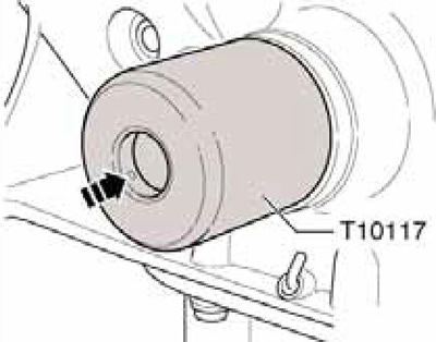
18.9 Installing the front oil seal
Rear oil seal (flange assembly)
Note: The oil seal flange with a polytetrafluoroethylene (PT-FE) seal is equipped with a support ring of the oil seal lip. This ring serves as the mounting sleeve, and must not be removed before the flange is installed. The flange, oil seal and rotor of the SCR sensor are one unit, and can only be replaced in assembly. After removal from the package, the flange and rotor of the SCR sensor must not rotate or separate from each other.
10. Remove the flywheel disc (similar to the 3.6L engine, see Section 8) and an intermediate plate (9 in illustration 8.1).
11. Turn the crankshaft clockwise to the TDC position of piston No.1 without removing the threaded camshaft covers (see section 19).
12. Remove the engine oil pan (see Section 13).
13. Remove the SMR sensor (see accompanying illustration).
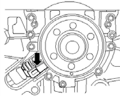
18.13 SCR sensor
14. Remove the bolts securing the sealing flange on the rear side of the engine. Screw them into the threaded (not fastening) sealing flange holes three bolts M6x35 (see accompanying illustration) and, alternately tightening them by half a turn per approach, squeeze out the flange together with the CKP sensor rotor and the rear crankshaft oil seal.
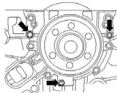
18.14 Sealing flange mounting bolts
15. The rotor of the CKP sensor is held in the installation position on the assembly device T10134 by a centering pin, and the installation device itself is held relative to the crankshaft by a guide pin inserted into a hole in the crankshaft. The parts of the device T10134 are shown in the accompanying illustration.
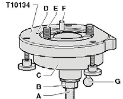
18.15 Assembly fixture parts T10134
A Fixed surface
In Gaika
With Assembly Case
D Centering pin
E Bolt
F Guide Pin for Diesel Engine (black handle)
G Guide Pin for Gasoline Engine (red handle)
16. Screw on the nut (In illustration 8.15) on the spindle thread so that the lower part of the surface to be fixed (A) is free. Clamp the T10134 device in a vice by the surface to be fixed.
17. Remove the retainer from the new flange (see accompanying illustration).
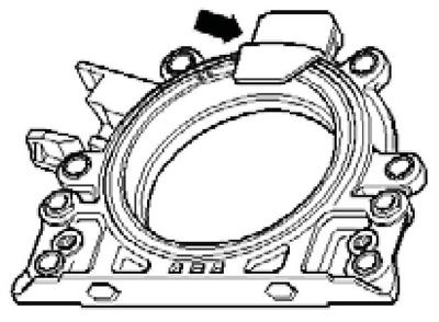
18.17 Flange retainer
18. Place the flange face down on a clean, flat surface and press down on the support ring (And on the accompanying illustration) sealing jaws in the direction of the arrow so that it rests on a flat surface. Do not remove or rotate the SKR sensor rotor.
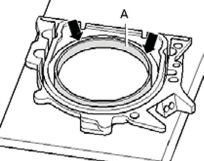
18.18 Pushing out the support ring (A)
19. Centering hole (In the accompanying illustration) on the rotor (C) must be aligned with the mark (A) on the flange, and the upper edge of the rotor and the front edge of the flange must be at the same level.
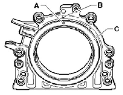
18.19 Centering hole (A) on rotor (C) and mark (B) on flange
20. Place the flange face down on the T10134 fixture so that the pin (In the accompanying illustration) entered the hole (A) of the rotor. Make sure that the flange rests with its plane on the device.
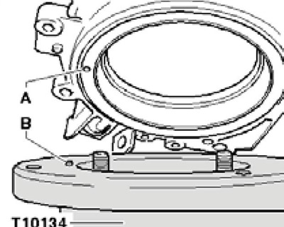
18.20 Installing the flange on the fixture
21. Screwing in three bolts (And on the accompanying illustration), press the support ring (B) against the surface of the T10134 tool to prevent the centering pin from slipping out of the hole in the rotor. Clean the crankshaft flange from oil and grease and make sure that piston No.1 is in the TDC position (see Section 10).
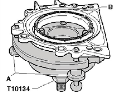
18.21 Fixing the flange to the fixture
22. Move the nut to the end of the spindle of the T10134 device. Align the flat side of the device body with the plane of the cylinder block mating with the oil pan, and secure the device to the shaft flange using bolts (And on the accompanying illustration).
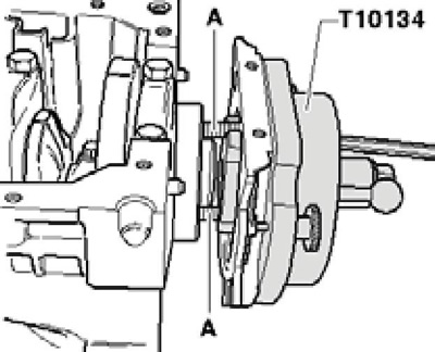
18.22 Initial attachment of the device to the shaft flange
23. To guide the flange with the seal, screw two M6x35 bolts into the cylinder block (And on the accompanying illustration) about 3 turns.
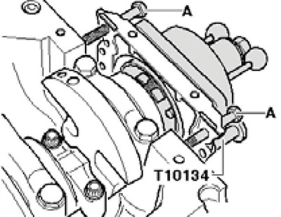
18.23 Bolts (A) for guiding the gland flange
24. Press down on the body of the device (With accompanying illustrations) by hand in the direction of the arrow so that the rotor (B) rests on the crankshaft flange (A). Fully insert the guide pin (F) with the red handle into the threaded hole in the crankshaft. When the guide pin is inserted correctly, its handle is located at a distance of approximately 10 mm from the housing of the assembly device. This positions the rotor of the CKP sensor in its final installation position.
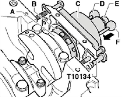
18.24 Final fastening of the device on the shaft flange
25. Tighten the assembly tool nut to 35 Nm using the VAG1331 torque wrench and VAG1332/11 socket (see accompanying illustration).
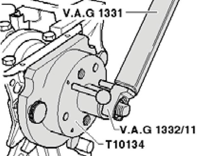
18.25 Pressing the rotor onto the shaft
Note: After tightening the nut to the specified torque, there should still be a small air gap between the cylinder block and the oil seal flange.
26. Move the nut (E in the illustration) t10134 fixture on the end of the spindle, unscrew the two bolts (A) from the cylinder block, unscrew the three bolts (B) from the flange, and also two bolts (And in illustration 8.32). Remove the assembly jig and support ring.
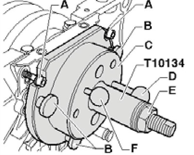
18.26 Removing the device
27. The rotor is installed correctly if there is a space between the shaft flange (And on the accompanying illustration) and the rotor (B) have a distance (a) of 0.5 mm. If the actual distance is too small, press the rotor again (see paragraphs 31-33); if the specified distance is reached, tighten the new flange mounting bolts in a diagonal sequence with a force of 10 Nm.
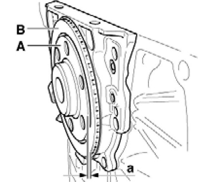
18.27 Checking the rotor position
28. Install the CKP sensor and tighten its bolt to 5 Nm.
29. Install the engine oil pan (see Section 13) and an intermediate plate.
30. Install the flywheel (see subsection above).
31. Secure the T10134 tool to the shaft flange using two bolts (And in illustration 8.22).
32. Screw in three bolts (In illustration 8.26) and insert the guide pin (F) with the red handle until it stops (there should be a distance of approximately 10 mm between the handle and the T10134 device).
33. Tighten the nut on the spindle of the assembly tool to 40 Nm and complete the installation as described in paragraphs 26-30. If the distance between the rotor and the shaft flange is again too small, tighten the nut to 45 Nm when pressing the rotor again.
Data taken from this portal SKODABOOK.ru