



Contents: Generator ⬇ Voltage regulator ⬇
Generator
1. Disconnect the negative battery cable (see Section 11).
2. Remove the accessory drive belt (see Chapter 2).
3. On TDI-CR diesel models, remove the top engine cover, remove the air cleaner and set it aside.
4. Remove the sound insulation under the engine compartment (see Chapter 11).
5. On TDI-CR diesel models, remove the engine cooling system radiator (see Chapter 3), as well as a hose and a boost air tube (see Chapter 4).
6. Remove and secure the refrigeration compressor to the hood lock holder without disconnecting the refrigerant lines from it (see Chapter 3).
7. Remove the protective cap of the B+ terminal nut and remove this nut (1 on the accompanying illustration). Disconnect the connector (2), remove the nut (3) from the holder and set it aside.
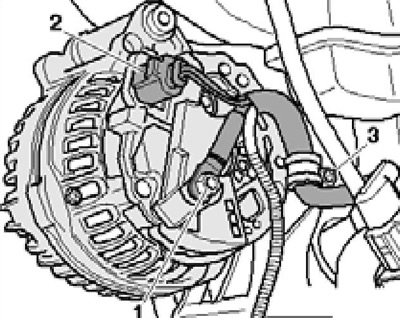
14.7 Generator connections
8. On a 3.6L engine, remove the bolt (1 on the accompanying illustration) and remove the tension roller (2).
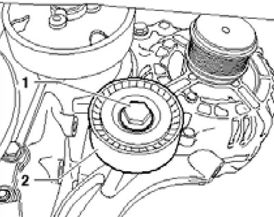
14.8 Tensioner roller bolt (3.6L engine)
9. Remove the bolts (see accompanying illustration). On the 3.6L petrol engine and TDI-CR diesel engines, remove the alternator downwards, and on the others, upwards.
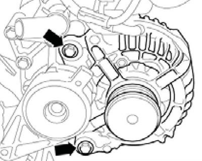
14.9a Generator fastening (the generator is mounted in the front)
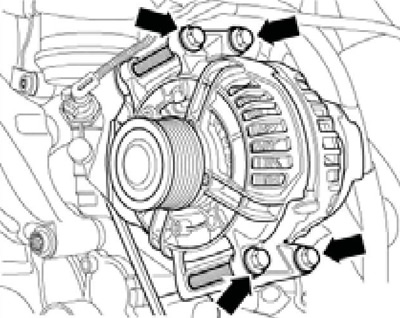
14.9b Generator Fasteners (the generator is mounted on the side)
10. Installation is carried out in the reverse order. If the generator is mounted at the front, move the bushings to facilitate its installation (And on the accompanying illustration) approximately 3 mm in the direction of the arrows. Tighten the tension roller bolt to 50 Nm.
[Text copied from this resource: skodabook]
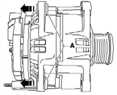
14.10 Preparing for generator installation
Voltage regulator
11. On the Valeo generator, remove the cover from the back side (see illustration 14.9a), remove the bolts (1 in Figure 14.9 B), loosen the nut (2) and remove the voltage regulator.
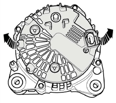
14.11a Valeo Generator Protective Cover Fasteners
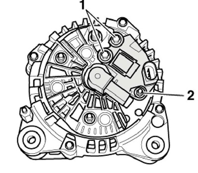
14.11b Fastening of the voltage regulator of the generator Valeo
12. On the generator of the company "Bosch" loosen the nuts (And in illustration 14.10a), unscrew the bolt (B) and remove the cover, then unscrew the bolts (see illustration 14.10b) and remove the voltage regulator. When installing, tighten the regulator bolts with a force of 2 Nm, the cover bolt with a force of 3 Nm, and the M6 // M8 cover nuts with a force of 12 // 30 Nm.
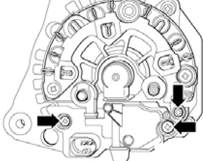
14.12a Fastening of the Bosch generator voltage regulator
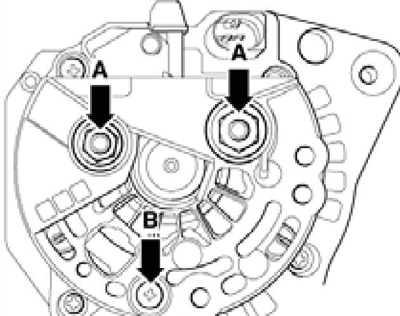
14.12b Bosch Generator Protective Cover Fasteners