



Contents: Petrol models 1.2 l ⬇ Petrol models 1.4 l ⬇ Petrol models 1.8 l ⬇ Diesel models 2.0 l (engines CFHC,…⬇
Petrol models 1.2 l
1. Prepare the VAG1590 or MP1-308 key and bore the corners of its triangle to size (and in the illustration) not less than 1 mm.
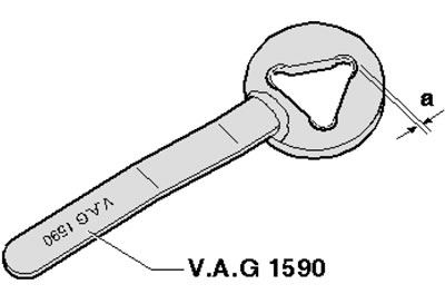
4.1. Refinement of the MP1-308 device
2. Remove the accessory drive belt (see Chapter 2).
3. Remove the bolts (see illustration) and remove the holder from the camshaft housing.
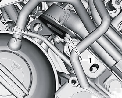
4.3. Removing the holder
Note: This bracket serves as transport protection for the engine until first installation and does not need to be installed.
4. Holding the pulley from turning with the VAG1590 or MP1-308 key, unscrew the three bolts and remove the coolant pump pulley (see illustration).
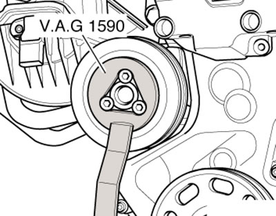
4.4. Removing the coolant pump pulley
Note: When installing, tighten the bolts to 20 Nm.
5. If necessary, after removing the pulley, you can remove the coolant pump as described below.
6. Drain the coolant from the engine cooling system (see Section 2).
7. Disconnect the vacuum line from the coolant pump (1 in the illustration) solenoid valve "N492" of the cooling circuit, unscrew the bolts (arrows) and remove the coolant pump.
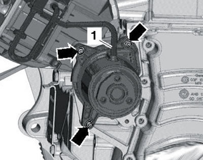
4.7. Removing the coolant pump
8. Installation is carried out in reverse order. Tighten the coolant pump mounting bolts to 9 Nm.
Petrol models 1.4 l
9. The installation details of the coolant pump and coolant circulation pump are shown in the illustration.
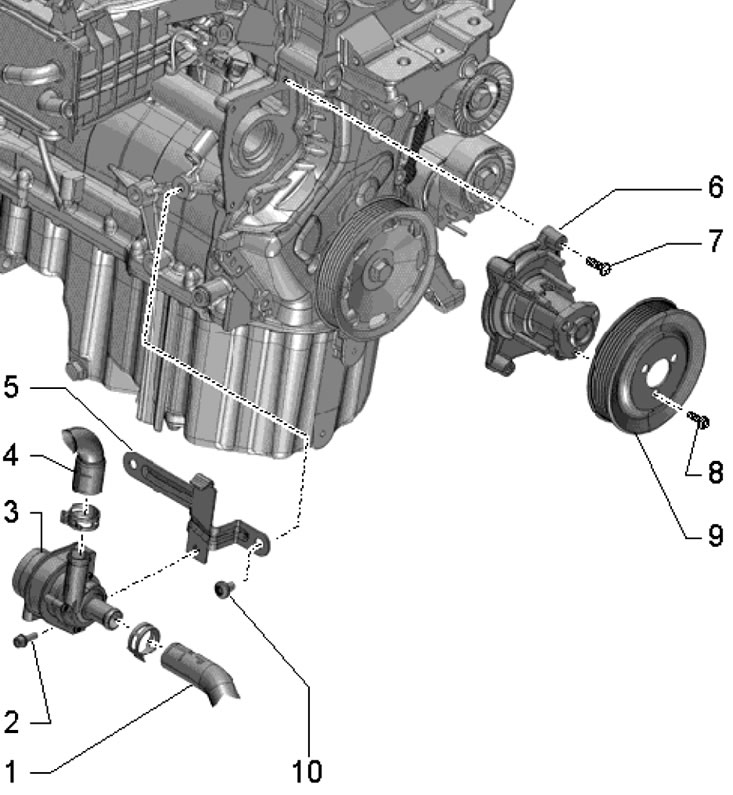
4.9. Installation details of the coolant pump and thermostat for 1.4 l petrol engines 1. Coolant hose; 2. Bolt, 8 Nm; 3. Coolant circulation pump "V50"; 4. Coolant hose; 5. Support; 6. Coolant pump, with built-in gasket; 7. Bolt, 9 Nm; 8, 10. Bolt, 20 Nm; 9. Coolant pump pulley
10. Removal of the coolant pump is carried out in the same way as removal of the coolant pump of a 1.2 l petrol engine (see subsection above).
Petrol models 1.8 l
11. The installation details of the coolant pump and its components are shown in the illustration.
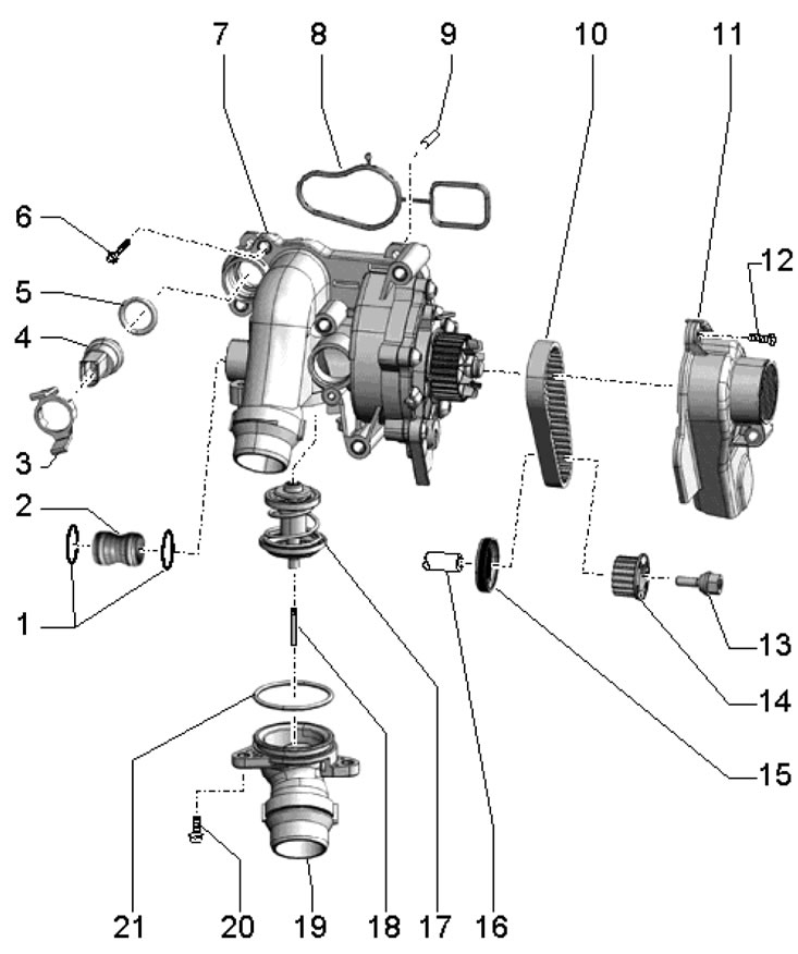
4.11. Coolant pump and thermostat installation details 1, 5, 21. Sealing ring, subject to replacement; 2. Connection; 3. Retainer; 4. Sensor ECT "G62"; 6, 12, 20. Bolt, 9 Nm; 7. Coolant pump; 8. Gasket, subject to replacement; 9. Centering pin; 10. Coolant pump drive belt; 11. Belt cover 10; 13. Left-hand thread bolt, to be replaced, 10 Nm, then tighten to 90°; 14. Water pump gear; 15. Water pump seal; 16. Balance shaft; 17. Thermostat, starts opening at 87°C, finishes opening at 105°C, stroke 8 mm; 18. Mounting pin; 19. Thermostat housing
12. Remove the small coolant pipe (see Section 7).
13. Loosen the coolant hose (2 in the illustration) and the wiring harness (1). Remove the bolt (arrow) and remove the bracket.
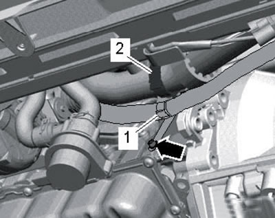
4.13. Coolant hose and electrical wiring bracket
14. Unscrew the bolt (2 in illustration 23.26 Chapter 2) on the bracket of the coolant circulation pump "V51".
15. Disconnect the coolant hoses (see illustration) and put them aside.
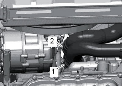
4.15. Coolant hoses
16. Remove the right front wheel arch liner (see Chapter 11).
17. Remove the bolts (arrows in illustration 25.4 Chapter 2). lift the clamps (1 and 2) and remove the air pressure tube.
18. Give the oil intake fasteners (see illustration 32.3 Chapter 2) and close the resulting hole to prevent dirt from getting into it.
19. Remove the bolts (see illustration) and remove the coolant pump drive belt cover.
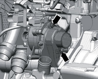
4.19. Fastening the coolant pump drive belt cover
20. Using the VAG1331 key and the T10360 insert, loosen the bolt (with left-hand thread) gear wheel fastenings (1 in the illustration) coolant pump, while holding the gear wheel from above to prevent it from turning. Remove the toothed wheel and belt (2) of the coolant pump drive.
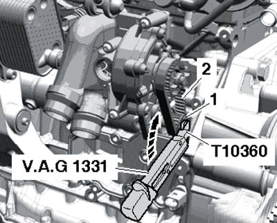
4.20. Removing the coolant pump drive belt
21. If necessary, replace the coolant pump seal after removing the coolant pump belt. Note: The inscription "Air side" or "Outside" on the seal must be read from the top.
22. If necessary, after removing the coolant pump belt, remove the coolant pump itself, as described below.
23. Disconnect the connector (1 in the illustration), unscrew the bolts (arrows) and remove the throttle module "J338".
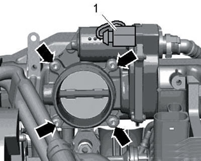
4.23. Connector and fastening of the throttle module
24. Disconnect the connector (1 in illustration 7.5) EST sensor.
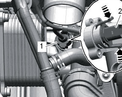
4.24. Removing the ECT sensor
25. Remove the bolts (1-5 in the illustration) and remove the coolant pump from the centering pins and pull it out of the oil cooler.
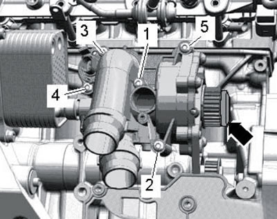
4.25. Coolant pump mounting bolts
26. Installation is carried out in reverse order. Use a new coolant pump sprocket mounting bolt, as well as new gaskets and O-rings. Before installing the coolant pump, make sure that both of its centering pins are inserted into the cylinder block and insert the connection (2 in illustration 4.11) into the oil cooler. Tighten the oil pump mounting bolts in the following sequence: (1-5 in illustration 4.25). When installing a new coolant pump, remove the protective cap (arrow) from it.
Diesel models 2.0 l (engines CFHC, CFJA, CLCB)
27. The installation details of the coolant pump and 4/2-way valve with thermostat are shown in the illustration. To remove the coolant pump, it is necessary to remove the timing belt (see Chapter 2).
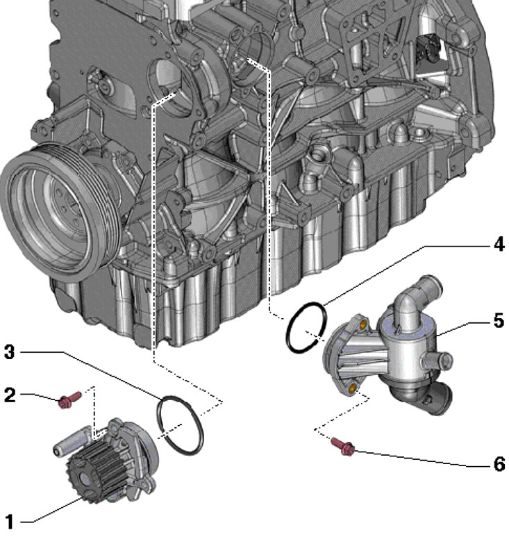
4.27. Installation details of the coolant pump and 4/2-way valve with thermostat 1. Coolant pump; 2.6. Bolt, 15 Nm; 3.4. Sealing ring, subject to replacement; 5. 4/2-way valve combined with thermostat (separate replacement is not provided)
Text obtained from the website: SkodaBook.ru