
Company vehicles Hyundai Company vehicles Kia Company vehicles Lada Company vehicles Mazda Company vehicles Mercedes-Benz Company vehicles Opel Company vehicles Mitsubishi
English Русский
Български
Беларускі
Український
Српски
Hrvatski
Română
Polski
Slovenský
Magyar
Articles   
Bookmark Contacts Sitemap
SkodaBook.ru


Fabia Rapid Octavia Superb Kodiaq Yeti Others
Yeti (2009-2017)

Removal and installation the thermostat (Skoda Yeti 5L)

  • Main
  • Yeti
  • 5L (2009-2017)
  • Power unit
  • Cooling system
  • Removal and installation the thermostat
0
Contents: Petrol models 1.8 l ⬇ Diesel models 2.0 l (engines CFHC,…⬇
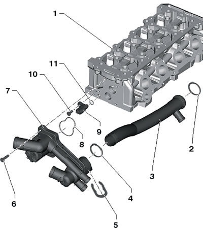
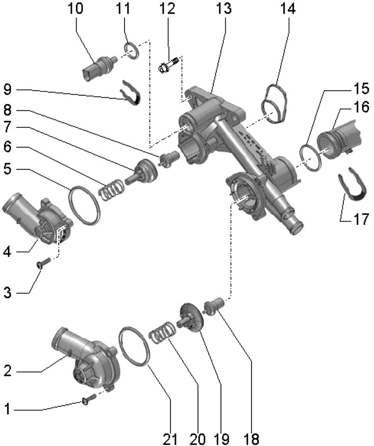
1. The thermostat installation details for 1.2L and 1.4L petrol models are shown in the illustrations.

6.1a. Installation details of the thermostat for…

6.1a. Installation details of the thermostat for 1.2 l petrol engines 1. Cylinder head; 2, 4, 11. Sealing ring, subject to replacement; 3. Coolant pipe; 5. Coolant pipe retaining ring; 6. Bolt, 11 Nm; 7. Thermostat housing; 8. Gasket, subject to replacement; 9. Sensor ECT "G62"; 10. Bolt, 10 Nm.

6.1b. Installation details of thermostats for 1.4…

6.1b. Installation details of thermostats for 1.4 l petrol engines. 1, 3. Bolt, 5 Nm; 2, 4. Connection; 5, 11, 15, 21. Sealing ring, subject to replacement; 6, 20. Spring; 7, 19. Pusher, do not tilt when installing; 8. Thermostat heating element, adjustable from 105°C to 120°C, stroke not less than 8 mm, do not swap with heating element 18; 9, 17. Retainer; 10. Sensor ECT "G62"; 12. Self-locking bolt, subject to replacement, 11 Nm; 13. Thermostat housing; 14. Gasket, subject to replacement; 16. Coolant pipe; 18. Thermostat heating element, adjustable from 83°C to 93°C, stroke not less than 8 mm, do not interchange with heating element 8.


Petrol models 1.8 l


2. Details of the installation of the coolant pump and thermostat are shown on illustrations 4.11.

3. Drain the coolant (see Section 2).

4. Press the clamps (see illustration 3.18) and remove the connection cover.

5. Remove the bolts (arrows in illustration 3.19) connections (1) and remove the connecting hose (2) from the guide.

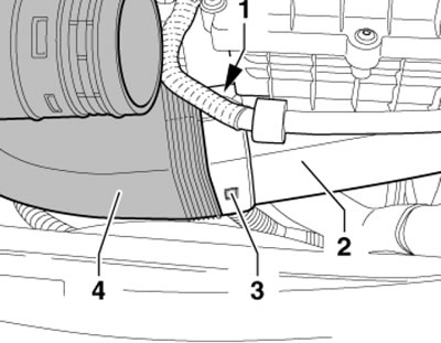
6. Press in the latches (1 and 3 in the illustration) and pull the connecting hose (4) out of the air cleaner (2).
6.6. Separating the connecting hose from the air…

6.6. Separating the connecting hose from the air cleaner.


7. Loosen the clamp (2 in illustration 23.16 Chapter 2), disconnect the connector (arrow) of the boost pressure sensor "G31", unscrew the bolts (1 and 4) and remove the pressure air tube with the hose from below.

8. Loosen the coolant hose (2 in illustration 4.13) and the wiring harness (1). Unscrew the bolt (arrow) and remove the bracket.

9. Unscrew the bolt (2 in illustration 23.26 Chapter 2) on the bracket of the coolant circulation pump "V51".

Note: The "V51" pump remains in the installation position.


10. Disconnect the coolant hoses (see illustration 4.15) and put them aside.

11. Give the oil intake fasteners (see illustration 32.3 Chapter 2) and close the resulting hole to prevent dirt from getting into it.


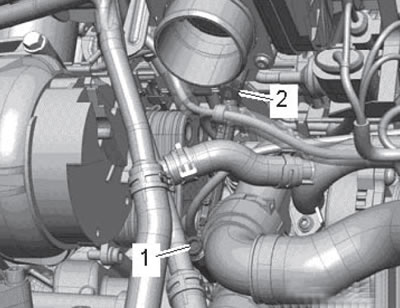
12. Loosen the nut (2 in the illustration), unscrew the bolt (1) and tilt the intake manifold support slightly to the right.
6.12. Fastening the intake manifold support.

6.12. Fastening the intake manifold support.


13. Remove the bolts (see illustration) and remove the thermostat housing. Remove the thermostat.
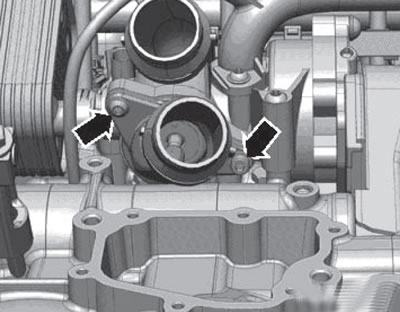
6.13. Thermostat housing fasteners.

6.13. Thermostat housing fasteners.


14. Prepare new O-rings and gaskets. Clean the sealing surface and wet the new O-rings with coolant.

15. Insert the thermostat (4 in the illustration) into the coolant pump housing (5) and tilt it slightly forward in the direction of the arrow. Carefully install the connection (3) by inserting the centering pin (2) into the guide (1).
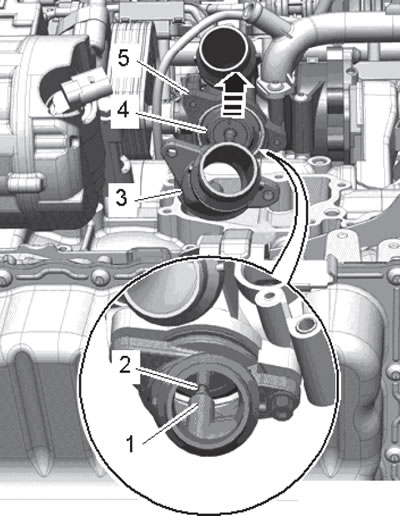
6.15. Installing the thermostat.

6.15. Installing the thermostat.


16. Further installation is carried out in reverse order.

Diesel models 2.0 l (engines CFHC, CFJA, CLCB)


17. Details of the installation of the coolant pump and 4/2-way valve with thermostat are shown on illustrations 4.27.

18. To remove the 4/2-way valve and thermostat assembly, you must:

Article reprinted from the website skodabook.ru
  • drain the coolant (see Section 2);
  • remove the air cleaner with the MAF sensor and intake hose (see Chapter 4);
  • remove the battery and its holder (see Chapter 5);
  • remove the left air pressure tube;
  • disconnect the coolant hoses.
This article is available at russian, bulgarian, belarusian, ukrainian, serbian, croatian, romanian, polish, slovak, hungarian
Article verified: Timur Komissarov
Share with friends:
◀ Previous
Skoda Yeti: Cooling system
Next ►

Removal and installation the coolant circulation pump
Removal and installation of the coolant pump and its parts
Removal and installation the radiator and its fans with the casing
Replacing the coolant, checking and adjusting its level, checking the…
General information and precautions
Removal and installation of sensors and some lines of the engine cooling…
Read similar articles on other Skoda models

➧ Removal and installation the thermostat Skoda Fabia 1 (1999-2007)
➧ Thermostat — External View (1.2L MPI Engine) Skoda Rapid 1 (2012-2022)
➧ Thermostat — General Information and Testing Skoda Octavia 1 (1996-2004)
➧ Removal and installation the thermostat Skoda Superb 2 (2008-2015)
➧ Thermostat (large circle) — removal and installation Skoda Kodiaq 1 (2016-2024)
➧ Thermostat — removal, checking for serviceability and installation Skoda Favorit (1987-1994)
Link to this article in various formats
Reviews and comments of visitors
No comments yet


Add two numbers: 30 + 18


Yeti (2009-2017) 
  • General information
  • Introduction to manual
  • Controls and instruments
  • Maintenance
  • Power unit
  • Petrol engine 1.2 l
  • Petrol engine 1.4 l
  • Petrol engine 1.8 l
  • Diesel engine 2.0 l
  • Cooling system
  • Power and control system
  • Exhaust system
  • Ignition and preheating systems
  • Starting and charging system
  • Transmission
  • Clutch
  • Manual gearbox
  • 7-speed gearbox DSG «0AM»
  • 6-speed gearbox DSG «02E»
  • Drive shafts
  • Chassis (running gear)
  • Brake system
  • Front suspension
  • Rear suspension
  • Steering
  • Body and interior
  • Heating and air conditioning
  • Exterior (external elements)
  • Interior (internal elements)
  • Electrical equipment
  • Equipment and devices
  • Lighting and signaling
  • Electrical diagrams
SkodaBook.ru © 2018–2026 | Mobile version | Articles on Skoda | Sitemap EN BG BY UA RS HR RO PL SK HU | Feedback | Site search | Bookmark
Fabia 1 (1999-2007) | Fabia 2 (2007-2014) | Rapid 1 (2012-2022) | Octavia 1 (1996-2004) | Octavia 3 (2013-2019) | Superb 2 (2008-2015) | Kodiaq 1 (2016-2024) | Yeti (2009-2017) | Favorit (1987-1994) | Felicia (1994-2001) |
By continuing to use the site, you agree to the use of cookies.