



Contents: Petrol models 1.2 l ⬇ Petrol models 1.4 l ⬇ Petrol models 1.8 l ⬇ Diesel models 2.0 l (engines CFHC,…⬇
Petrol models 1.2 l
1. The details of the radiator and its fan installation are shown in the illustration.
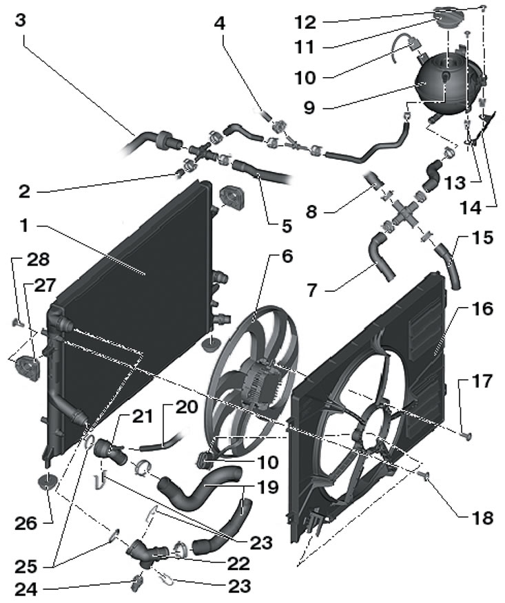
3.1. Details of installation of the radiator and its fan 1. Assembly of radiators (for intercooler and engine cooling system); 2, 4. Coolant hose, to turbocharger; 3. Coolant hose, to the intercooler radiator; 5. Coolant hose, to the intercooler in the intake manifold; 6. Radiator fan "V7", with control unit "J293"; 7. Coolant hose, to the coolant pipe under the intake manifold; 8. Coolant hose, to engine oil cooler; 9. Expansion tank, with sensor "G32" low coolant level; 10. Electrical wiring connector; 11. Tank lid 9; 12, 17, 18, 28. Bolt, 5 Nm; 13. Plastic inserts for bolts; 14. Support; 15. Coolant hose, on the coolant circulation pump "V50"; 16. Fan shroud; 19. Coolant hose, on thermostat housing; 20. Coolant hose, to the heater radiator; 21. Connection, for upper coolant hose; 22. Connection, for lower coolant hose; 23. Retainer; 24. Sensor "G83" coolant temperature at the radiator outlet; 25. Sealing ring, subject to replacement; 26. Lower radiator support; 27. Upper radiator support
2. Remove the air cleaner (see Chapter 4).
3. Remove the upper fan shroud mounting bolts (see illustration), remove the sound insulation under the engine compartment (see Chapter 11), disconnect the connector (1) and unscrew the lower casing mounting bolts.
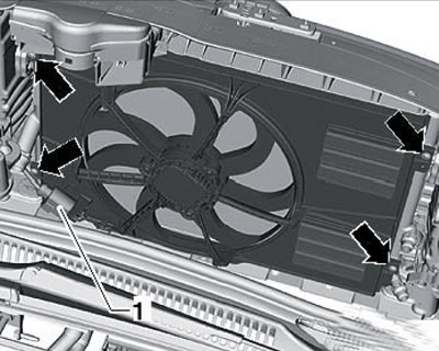
3.3. Fan shroud fastening
4. Remove the fan shroud downwards. If necessary, remove the bolts (see illustration) and remove the fan "V7".
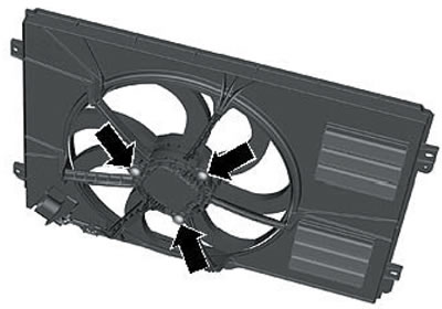
3.4. Fastening the fan to the casing
5. If necessary, after removing the fan shroud, the radiator can be removed as described below.
6. Drain the coolant (see Section 2).
7. Lift the latch (see illustration 15.6 Chapter 2) and remove the upper left connection from the radiator.
8. Remove the upper right coolant hose connection for the intercooler radiator.
9. Remove the front bumper (see Chapter 11).
10. Remove the headlights (see Chapter 12).
11. Remove the bolts (2 in illustration 3.11a) and (arrows in illustration 3.11b) refrigeration unit condenser fastenings.
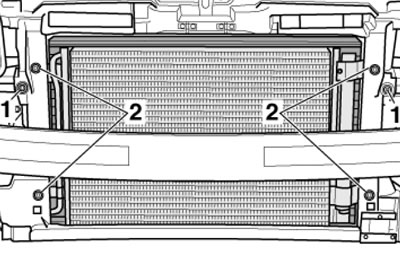
3.11a. Fastening the condenser (2) and radiator (1)
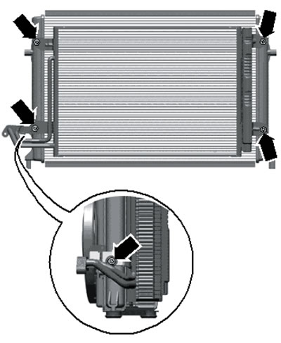
3.11b. Capacitor mounting
Note: Do not disconnect, kink or pull the refrigerant lines.
12. Remove the bolts (1 in illustration 3.11a) radiator mounts, tilt it back slightly and remove it upwards.
13. Installation is carried out in reverse order.
Petrol models 1.4 l
14. The details of the installation of the radiator and its fans are shown in the illustration.
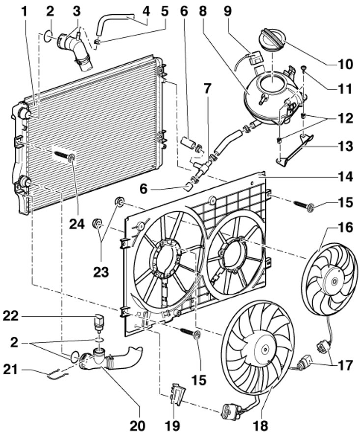
3.14. Details of installation of the radiator and its fans 1. Radiator; 2. Sealing ring, subject to replacement; 3. Upper coolant hose, to cylinder head; 4. Coolant hose, to the expansion tank; 5. Spring clamp; 6. Coolant hose, to coolant pipe for intercooler radiator; 7. Connecting tube; 8. Expansion tank, with sensor "G32" low coolant level; 9, 17. Electrical wiring connector; 10. Tank lid 8; 11. Bolt, 3 Nm; 12. Plastic inserts for bolts; 13. Support; 14. Fan casing; 15. Bolt, 5 Nm; 16. Right radiator fan "V35"; 18. Radiator fan "V7", with control unit "J293"; 19. Connector holder; 20. Lower coolant hose, to thermostat housing; 21. Retainer; 22. Sensor "G83" coolant temperature at the radiator outlet; 23. Nut, 5 Nm; 24. Intercooler radiator bolt, 5 Nm
15. To remove the fan casing, it is necessary to remove the air cleaner (see Chapter 4).
16. The radiator is removed only after removing the fan casing and draining the cooling system.
Petrol models 1.8 l
17. The details of the installation of the radiator and its fans are shown in the illustration. To remove the fan shroud, follow the steps in paragraphs 18-20. To remove the radiator, proceed to paragraph 21.
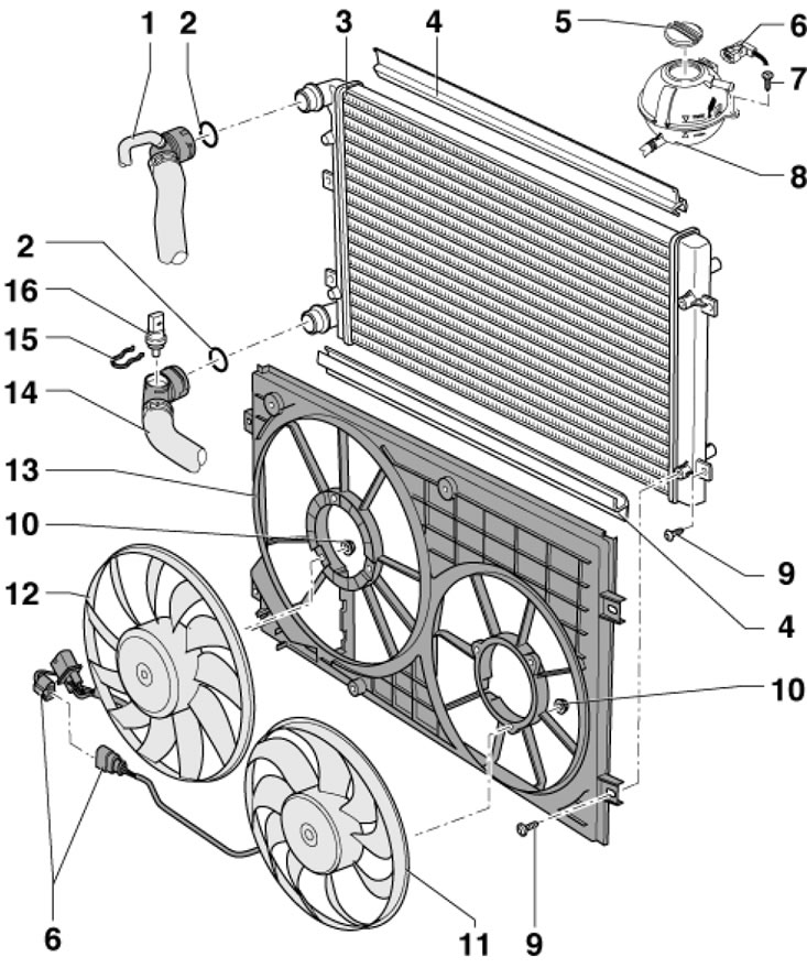
3.17. Details of installation of the radiator and its fans 1. Upper coolant hose, to coolant pump; 2. Sealing ring, subject to replacement; 3. Radiator; 4. Gasket, subject to replacement; 5. Tank lid 8; 6. Electrical wiring connector; 7. Bolt, 3 Nm; 8. Expansion tank, with sensor "G32" low coolant level; 9. Bolt, 5 Nm; 10. Nut, 10 Nm; 11. Right radiator fan "V35"; 12. Radiator fan "V7", with control unit "J293"; 13. Fan casing; 14. Lower coolant hose, to thermostat housing; 15. Retainer; 16. Sensor "G83" coolant temperature at the radiator outlet
18. Press the clamps (see illustration) and remove the connection cover.
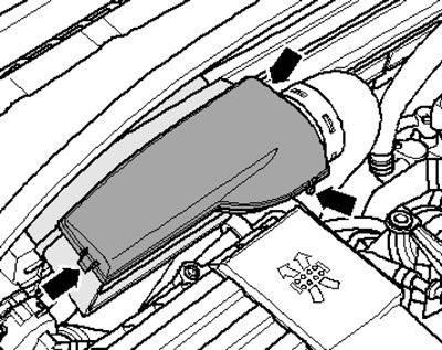
3.18. Joint cover fasteners
19. Remove the bolts (arrows in the illustration) connections (1) and remove the connecting hose (2) from the guide.
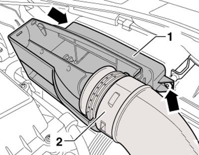
3.19. Fastening the connection
20. Remove the upper fan shroud bolts (arrows in the illustration), remove the sound insulation under the engine compartment (see Chapter 11), disconnect the connector (1), unscrew the lower casing bolts and remove it.
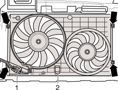
3.20. Fan casing fastening
21. Drain the coolant (see Section 2).
22. Disconnect the connector (1 in the illustration) and remove the fan shroud (see paragraphs 18-20).
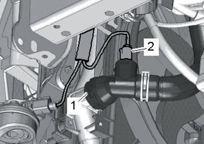
3.22. Connector (2)
23. Disconnect the coolant lines from the radiator at the top and bottom.
24. Remove the bolts (1 and 2 in the illustration) and remove the radiator downwards.
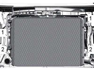
3.24. Radiator fastening
25. Installation is carried out in reverse order. When installing a new radiator, replace the coolant.
Diesel models 2.0 l (engines CFHC, CFJA, CLCB)
26. The details of the installation of the radiator and its fans are shown in the illustration.
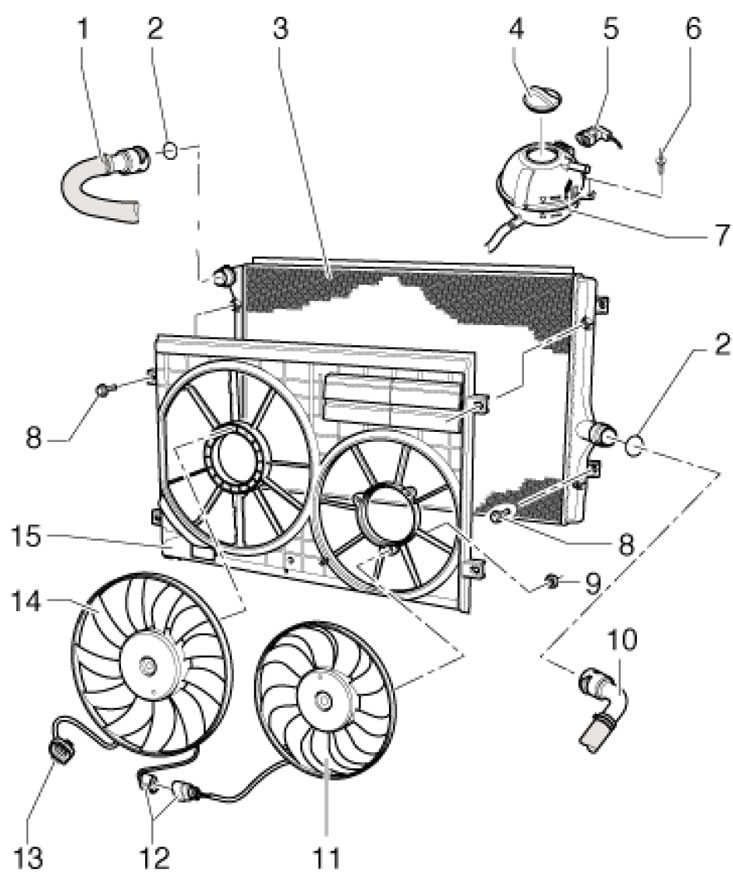
3.26. Details of installation of the radiator and its fans 1. Upper coolant hose, to cylinder head; 2. Sealing ring, subject to replacement; 3. Radiator; 4. Tank lid 7; 5, 12, 13. Electrical wiring connector; 6. Bolt, 3 Nm; 7. Expansion tank, with sensor "G32" low coolant level; 8. Bolt, 5 Nm; 9. Nut, 5 Nm; 10. Lower coolant hose, to 4/2-way valve and thermostat housing; 11. Right radiator fan "V35"; 12. Radiator fan "V7", with control unit "J293"; 13. Fan casing
27. To remove the fan casing, it is necessary to remove the left air pressure hose (see Chapter 4).
28. The radiator is removed only after removing the fan casing and draining the cooling system, similar to the 1.8 l engine (see above).