



Contents: Removal and installation the handle…⬇ Replacing the gear selector cable tip ⬇ Removal and installation the slot…⬇ Replacing the gear selector cable tip ⬇ Removal and installation the gear…⬇ Removal and installation cables ⬇ Disassembling and assembling the…⬇ Checking and adjusting cables ⬇
1. The installation details of the gear shift drive components are shown in the illustrations. Apply grease G 000 450 02 to the friction points.
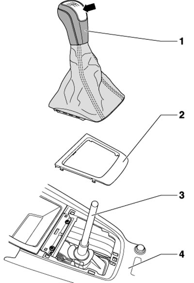
4.1a. Handle and dust cover installation details Arrow Cover, can be separated from the handle with 1 screwdriver; 1. Handle with dust cover, can only be replaced together; 2. Overlay; 3. Gear shift lever; 4. Center console
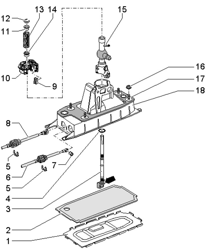
4.1b. Gear Shift Lever Assembly Installation Details 1. The support plate with bending tabs is subject to replacement; 2. Seal, subject to replacement; 3. Gear shift lever with guide, can be removed/installed without removing guide 15; 4. The insulating washer is pressed onto the lever until it stops (arrow); 5. Lock washer, must be replaced, do not damage the cables when removing; 6. Gear selection cable; 7. Cable bushing 6; 8. Groove selection cable; 9. Damper; 10. The hinge socket is damaged when removed and must be replaced; 11, 14. Bushing; 12. Lock washer; 13. Spring; 15. Lever guide 3; 16. Nuts, 4 pcs., 8 Nm (Mb) or 25 Nm (M8); 17. Self-adhesive seal between the body 18 and the bottom (glued to the body 18); 18. Gear shift lever housing, non-separable unit with compression spring and slot selection lever
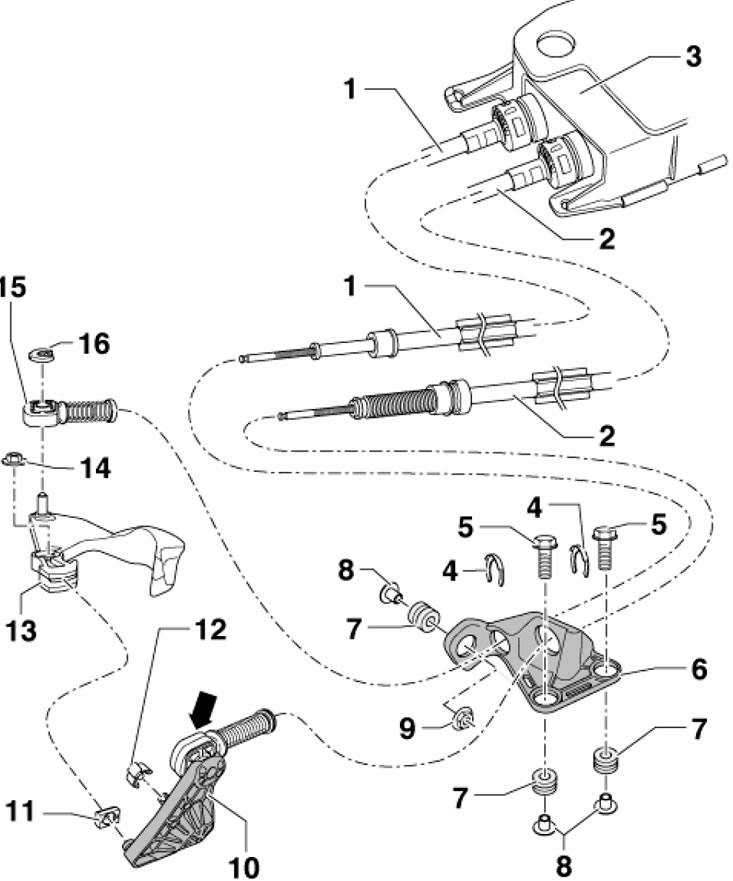
4.1c. Details of installation of cables of manual transmission "02Q" 1. Gear selection cable, connects to lock 15; 2. Groove selection cable, connects to lock 10; 3. Gear shift lever housing; 4. Lock washer, must be replaced, do not damage the cable when removing; 5. Holder bolts 6, 2 pcs.; 6. Plastic cable holder; 7. Holder bushings 6; 8. Spacer; 9. Holder nut 6, 20 Nm; 10. Lever for selecting the groove with a tip (arrow) of the cable 2, made of plastic, with a hole with a diameter of 10 mm; 11. Sliding shoe; 12. Lever lock on the gear shift unit cover; 13. The gear selector lever, with the balancing weight, is inserted so that the missing tooth coincides with the selector shaft; 14. Nut, 23 Nm, subject to replacement; 15. Cable end 1, on lever 13, with a hole of 8.5 mm diameter; 16. Lock washer, subject to replacement
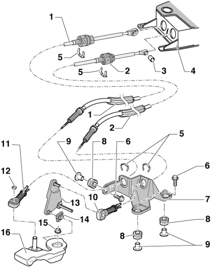
4.1d. Details of installation of cables of the manual transmission "OAJ" 1. Gear selection cable, connects to tip 11; 2. Groove selection cable, connects to tip 10; 3. Cable bushing 2; 4. Gear shift lever housing; 5. Cable retainer, subject to replacement; 6. Bracket mounting bolts 7, subject to replacement, 3 pcs., 20 Nm; 7. Cable bracket; 8. Gaskets, 3 pcs.; 9. Bushings, 3 pcs.; 10. Tip for fastening cable 2 on lever 13, do not swap with tip 11; 11. Tip for fastening cable 1 on lever 16, do not swap with tip 10; 12. Lock washer, subject to replacement; 13. Groove selection lever, removed/installed together with tip 10; 14. Shoe; 15. Self-locking nut, 23 Nm, subject to replacement; 16. Gear selection lever
Removal and installation the handle with dust cover
2. Carefully pry up the dust cover (And in the illustration) together with the cover (B) from the central console (C) in the direction of the arrow using the wedge T30098. Turn the boot inside out through the handle.
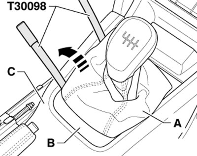
4.2. Separating the boot from the center console
3. Turn the locking mechanism (1 in the illustration) 45° in the direction of the arrow and pull the handle with the dust cover (2) from the lever (3).
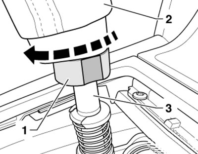
4.3. Removing the handle with dust cover
4. To install, unscrew the boot (1 in the illustration), and press the handle together with the dust cover onto the lever (2) as far as possible. Turn the locking mechanism 45° in the direction of the arrow so that the surface (4) faces one of the front seats. Unscrew the boot and fix it together with the trim in the center console.
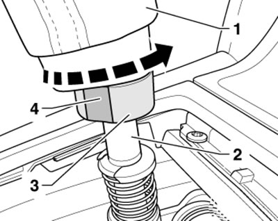
4.4. Installing the handle with dust cover
Replacing the gear selector cable tip
5. Remove the cable lock at the tip (And in the illustration). To do this, slide the sleeve all the way in the direction of the arrow (1) and turn the sleeve all the way in the direction of the arrow (2) until you hear it lock.
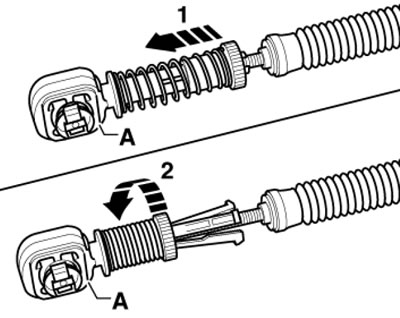
4.5. Removing the gear selection cable fixation in the tip
6. Remove the lock washer (1 in the illustration) cable from the gear selection lever (2) and pull the cable off the axle (arrow). Apply a little grease G 000 450 02 to the axle and secure the cable to it using a new lock washer (1). Finally, adjust the gearshift drive (see the relevant subsection below).
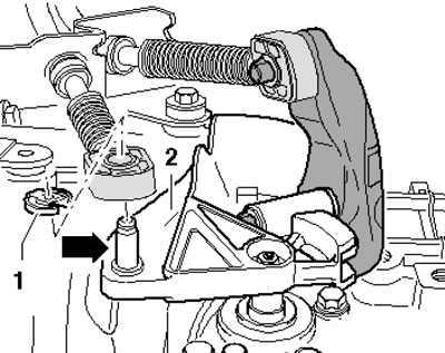
4.6. Removing the gear selection cable tip
Removal and installation the slot selection lever
7. Remove the cable lock from the tip. To do this, move the sleeve until it stops in the direction of the arrow (1 in the illustration) and turn the sleeve all the way in the direction of the arrow (2) until you hear it lock into place.
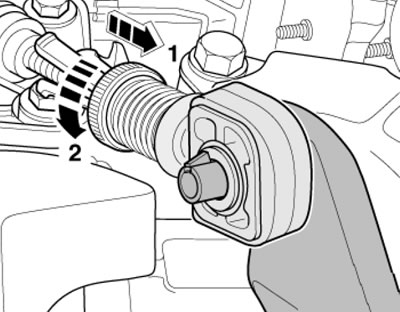
4.7. Removing the slot selection cable lock in the tip
Note: To avoid damaging the cable, the cable end must be separated from the cable before removing the slot selector lever. The gear selector lever must be in neutral position. The tip can only be removed/installed when the lever is removed (see subsection below).
8. If the lever (And in the illustration) is secured to the cover with a holder, carefully press it until it stops in the direction of the arrow (1) and, moving the lever back and forth in the direction of the arrow (2), pull it out together with the tip (B) of the cable in the direction of the arrow (3).
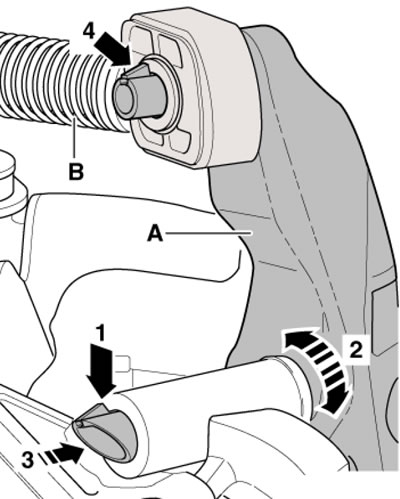
4.8. Removing the groove selection lever (option 1)
9. If the lever (With in the illustration) is secured to the cover with a lock (A), press this lock and remove the lever together with the cable end (D). If you cannot remove the cable, you may need to remove the manual transmission console (E).
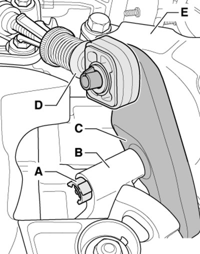
4.9. Removing the groove selection lever (option 2)
10. Installation is carried out in reverse order. Pre-lubricate the rubbing surfaces with grease G 000 450 02.
Replacing the gear selector cable tip
11. Remove the groove selection lever (see subsection above), insert a screwdriver (And in the illustration) between the sleeve (B) and the lever and press out the tip.
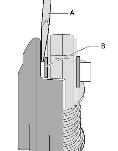
4.11. Removing the gear selection cable tip
12. With the lever removed, push the tip onto the lever until the retainer pops out (4 in illustration 4.8). The tip should fit onto the lever freely.
Removal and installation the gear shift lever assembly
Note: The description is given using the example of models with manual transmission "02Q".
13. Disconnect the negative cable from the battery.
14. Remove the gear shift lever handle and boot (see paragraphs 2-3).
15. Remove the screws (And in the illustration) and remove the ashtray/storage compartment (B).
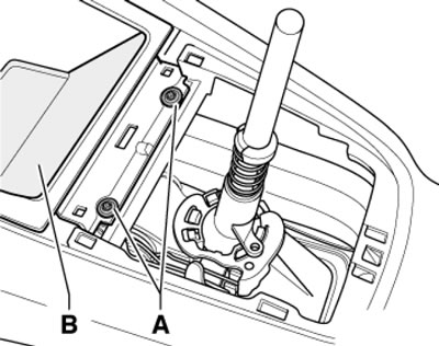
4.15. Ashtray/storage compartment fastening
16. Loosen the gear shift lever assembly mounting nuts (see illustration).
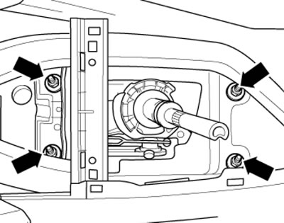
4.16. Lever assembly fastening nuts
17. Remove the air cleaner (see Chapter 4).
18. Remove the lock washer (1 in illustration 4.6) from the lever (2) and remove the gear selection cable from the axle (arrow).
19. Remove the gear selector lever (see paragraphs 7-9).
20. Give away the fasteners (see illustration) and remove the cable holder from the manual transmission. If present, remove the sound insulation under the engine compartment (see Chapter 11).
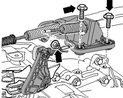
4.20. Fastening of the cable holder
21. Remove the bottom cover on the left and right (see illustration).
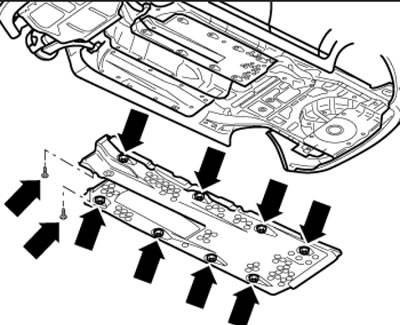
4.21. Bottom casing fastening
22. Remove the cross member (1 in the illustration) central tunnel. Remove the double clamp fastener (arrows), separate the exhaust system and remove it from the assembly holder. Support the front exhaust pipe and unhook the rear muffler (2) from the hangers.
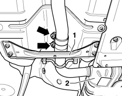
4.22. Double clamp fastener and central tunnel crossmember
Note: Do not bend the flexible section of the exhaust pipe more than 10°.
23. On AWD models, remove the front exhaust pipe (if necessary, see Chapter 4), remove the rear part of the exhaust system. Then remove the heat shield (2 in the illustration) cardan shaft and the cardan shaft itself (see Chapter 8).
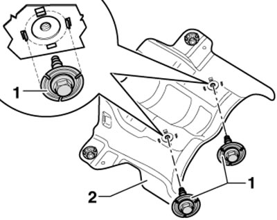
4.23. Fastening the heat shield of the cardan shaft
24. Remove the heat shield under the selector lever assembly, tilt the assembly down and remove it together with the cables. The installation is described below.
25. Display the assembly (2 in the illustration) lever parallel to the body (the distance to the body must be the same on both sides) and tighten its fasteners. Route the cables (1) from the lever assembly to the manual transmission parallel, without crossing, through the channels in the heat shield (3).
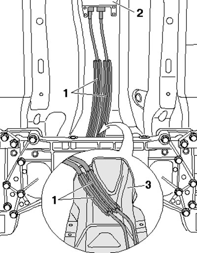
4.25. Laying cables
26. The cables and heat shield are held relative to each other by a clamp (And in the illustration).
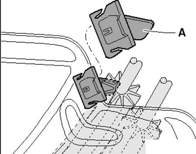
4.26. Cable and heat shield retainer
27. Apply to axle (arrow in illustration 4.6) some G000 450 02 grease and secure the cable to it using a new lock washer (1).
28. Install the groove selection lever (see paragraphs 7-10) and secure the cable in the tip.
29. On AWD models, install the driveshaft (see Chapter 8) and its heat shield.
30. Assemble the exhaust system, set it without tension and install the central tunnel cross member (see Part B Chapter 4).
31. Install the underbody covers and sound insulation under the engine compartment (see Chapter 11).
32. Install the ashtray/storage compartment.
33. Adjust the gear shift drive (see the relevant subsection below).
34. Install the dust boot with the gear shift lever handle (see paragraph 4).
35. Install the air cleaner.
Removal and installation cables
36. Remove the gear shift lever assembly (see subsection above), bend the tabs with a screwdriver (see illustration) and remove the lever assembly cover and its seal.
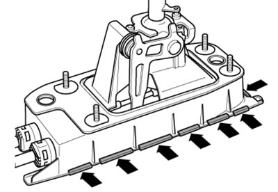
4.36. Lid fastening tabs
37. Remove the clamps (1 and 2 in the illustration) and press the slot selection cable (3) off the corner plate (4) and the cable (5) off the guide (6). Remove the cables from the gearshift lever assembly.
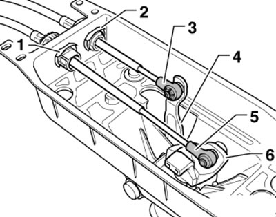
4.37. Cables on the lever assembly
38. Remove the ends from the cables. To do this, move the sleeve until it stops in the direction of the arrow (1 in illustration 4.5) and turn the sleeve all the way in the direction of the arrow (2) until you hear it lock into place.
39. Remove the clamps (1 and 2 in the illustration) and remove the support from the cables.
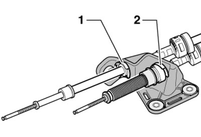
4.39. Cable clamps
40. Installation is carried out in reverse order. Finally, adjust the gear shift drive (see the relevant subsection below).
Disassembling and assembling the gear shift lever housing
41. Remove the gear shift lever assembly and remove the cables from it (see subsection above).
42. Raise the top edge (And in the illustration) springs above the tabs of the groove selection lever. Use a screwdriver to press the tabs (arrows) of the hinge socket towards the hinge of the lever guide. If necessary, break the hinge socket tabs.
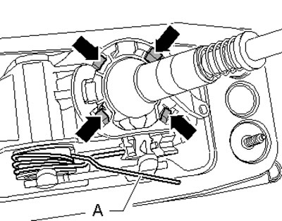
4.42. Preparing to remove the hinge socket
43. Pry up the hinge socket (And in the illustration) together with the lever guide and lever (B) and separate from the gear shift lever assembly. Then press the pivot socket away from the lever guide pivot and remove it.
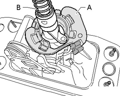
4.43. Removing the hinge socket
44. Move the lower edge of the spring onto the shoulder on the groove selection lever in the direction of the arrow (1 in the illustration) until it stops. Pull the lever guide up until it stops and pull the hinge pin out of the lever in the direction of the arrow (2). Pay attention to the guides (A) - they must not be broken.
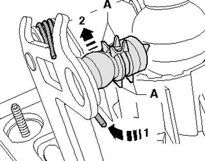
4.44. Removing the hinge
45. Turn the lever guide in the direction of the arrow (1 in the illustration) and tilt it together with the lever in the direction of the arrow (3). The pin (2) must be in the groove in the gearshift lever housing.
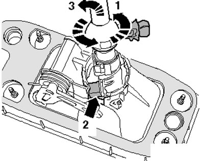
4.45. Removing the lever
46. During assembly, the lower end of the spring (1 in illustration 4.44) may slip off the groove selection lever arm. Therefore, you should carefully press the spring down from the shoulder. The ends of the spring are pulled diagonally with a loud noise.
47. Loosen the ends (A and B in the illustration) springs, turning them to the right - they should be facing in opposite directions.
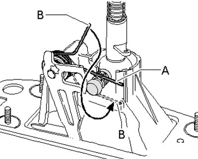
4.47. Spring installation position
48. Install the lever guide together with the lever into the gear shift lever housing. Turn the guide in the direction of the arrow (2 in the illustration), so that the pivot pin (A) is located above the groove in the gear shift lever housing. The pin (U) must also remain in the groove in the gear shift lever housing.
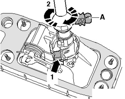
4.48. Installing the lever guide
49. Install the gear shift lever assembly with the lever guide into the larger hole in the T10083 fixture (see illustration). Note: If necessary, first remove the lever so that its housing with the guide can be inserted into the device. The lever guide must protrude completely upward from the gear shift lever housing.
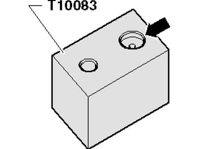
4.49. Device T10083
50. Insert the end (And in illustration 4.47) springs into the guide from above. Pull the end (B) of the spring down and insert it next to the guide (in the direction of the hinge joint). Carefully remove the lever assembly from the T10083 tool.
51. Move the groove selection lever all the way back, in the direction of the arrow (1 in the illustration). Lubricate the hinge pin with G000 450 02 grease and press it into the groove selection lever in the direction of the arrow (2). Do not damage the guides (A) and tabs (B).
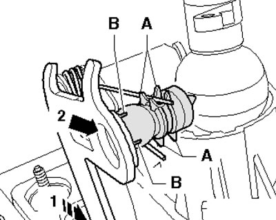
4.51. Installing the hinge pin
52. Reinstall the gearshift lever assembly with the lever guide into the larger hole in the T10083 tool (see illustration 4.49). The lever guide must protrude completely upward from the gear shift lever housing.
53. Raise the top edge (And in the illustration) springs above the finger of the groove selection lever. Lubricate the new pivot socket (B) and the guide pivot. Press the ball socket into the hinge until it stops. Remove the lever assembly from the T10083 tool and secure the pivot socket into the gearshift lever housing in four places (arrows). Insert the lower edge (C) of the spring into the guide, lift the upper edge (A) of the spring over the selector lever pin into the guide.
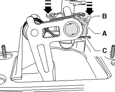
4.53. Installing the spring
54. Connect the cables and install the lever assembly (see subsection above).
Checking and adjusting cables
Note: The description is given using the example of models with manual transmission "02Q".
55. In neutral position, the lever should be in the slot between 3rd and 4th gears. If there is consistent difficulty in selecting gears with the clutch pedal depressed, adjust the cables as described above.
56. Before adjustment, make sure that the moving parts of the working elements and the elements transmitting force are in good condition. The selector mechanism must move freely. The manual transmission, clutch and clutch drive must also be in good working order.
57. Engage neutral position.
58. Remove the air cleaner (see Chapter 4).
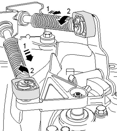
59. Pull the cable end sleeves until they stop in the direction of the arrows (1 in the illustration) and turn left in the direction of the arrows (2) to lock.
4.59. Removing the cable fixation
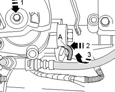
60. Fix the selector shaft. To do this, press it in the direction of the arrow (1 in the illustration), while simultaneously turning the corner rod (A) upwards (arrow 3) and pressing it in the direction of the arrow (2).
4.60. Fixing the selector shaft
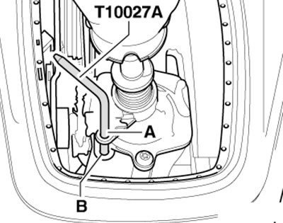
61. Remove the gearshift lever boot (see the relevant subsection above) and lock the lever in the neutral position by inserting the T10027A tool through the hole (And in the illustration) into the hole (B).
4.61. Lever locking
62. Turn the locking mechanisms of the cable ends in the direction opposite to the arrows (2 in illustration 4.59) until it stops, the springs will push the locking mechanisms in the direction opposite to the arrows (1) to their original position.
63. Move the corner rod to its original position against the arrows (2 and 3 in illustration 4.60), - the selector shaft should move.
64. Remove the T10027A device from the lever and check the adjustment (see paragraph 39).
65. Install the lever parts and air cleaner.
(Data taken from this portal SKODABOOK.ru)