



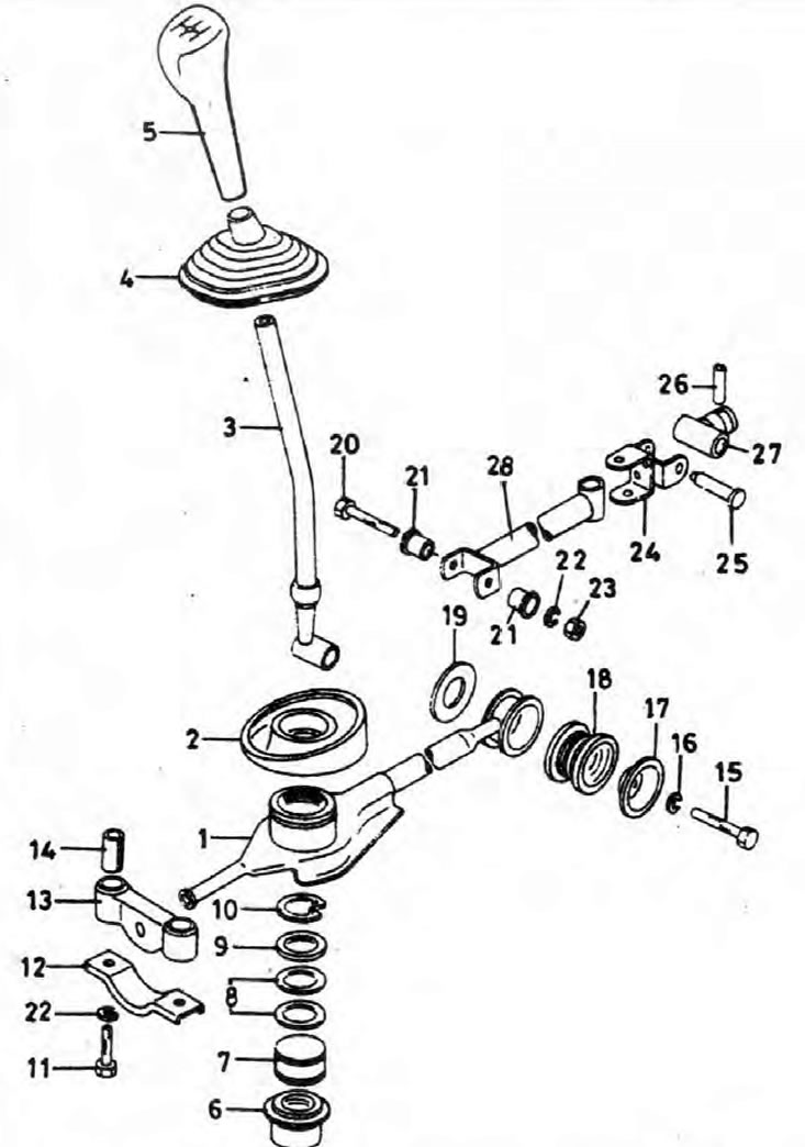
Pic. 7.1. Traction/Shifter Components
1. Stabilizer rod for gear shifting; 2. Upper cover of the stabilizer bar; 3. Gear lever; 4. Protective cover of the gear lever; 5. Gear lever handle; 6. Bottom protective cover; 7. Nest of installation of the lever of a gear change; 8. Washers; 9. Washer; 10. Retaining ring; 11. Bolt for fastening the stabilizer bar to the body; 12. Mounting plate; 13. Rubber cushion; 14. Spacer; 15. A bolt of fastening of a bar stabilizer to transmission; 16. Washer; 17. Washer; 18. Rubber cushion; 19. Washer; 20. A bolt of fastening of mobile draft to the gear lever; 21. Articulated bushing; 22. Washer; 23. Nut; 24. Mobile rod attachment; 25. Articulated pin for fastening the movable rod; 26. Cylindrical pin; 27. Front traction rod; 28. Rear traction rod.
Removing
1. Park your car on level ground (not slanted), turn off the ignition, make sure the transmission is in neutral and apply the handbrake. Jack up the front of the vehicle and place it securely on axle stands.
2. While working in the cabin, pull the handle off the shift lever.
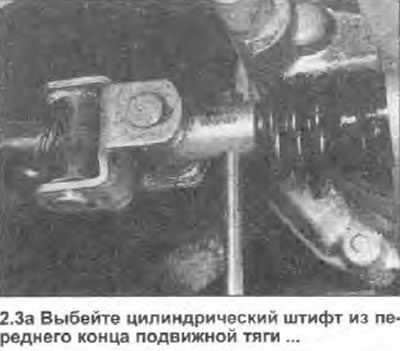
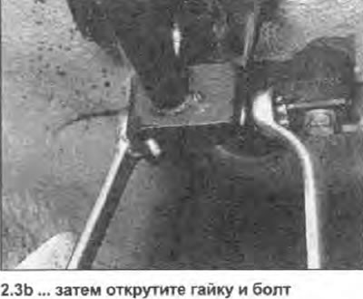
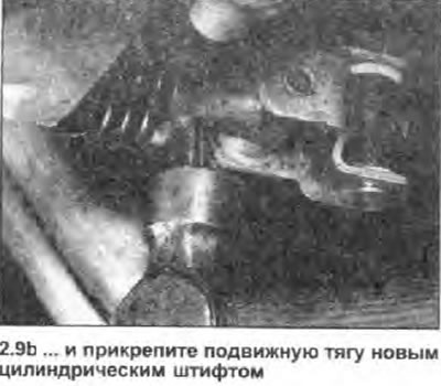
3. Working under the vehicle, use a hammer and a suitable punch to knock out the roll pin from the movable link and disconnect the link from the transmission. Discard the pin - it must be replaced. Loosen the nut and bolt holding the movable link to the shift lever, then remove the bolt and washers installed between these two components (see photo). Remove the movable link from under the vehicle.
 |  |
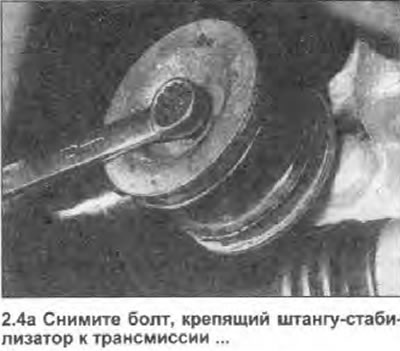
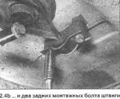
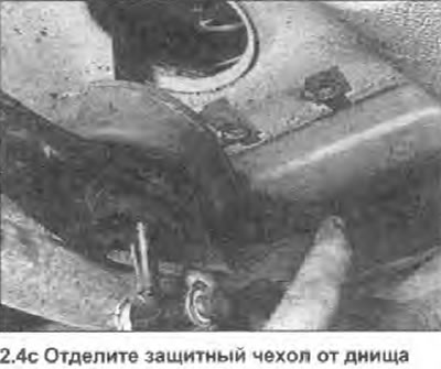
4. Loosen and remove the bolt securing the forward end of the shift linkage stabilizer bar to the transmission case, then separate the bar and remove the two large washers securing it. Unscrew the two bolts securing the rear of the stabilizer bar to the underside of the car and remove the bolts along with the mounting plate, not losing sight of the two spacers that are mounted on the rubber cushion. Separate the top rubber boot of the stabilizer bar from the bottom of the vehicle, then gently lower the bar and arm assembly down and out from under the vehicle (see photo).
 |  |
 |
5. If necessary, remove a protective cover of the gear lever.
Bulkhead
6. Remove the top cover of the stabilizer bar to gain access to the shift lever retaining ring. Remove retaining ring and remove washers. Use a mallet to knock out the shift lever up and separate it from the stabilizer bar, then remove the lever socket and lower protective cover.
7. Thoroughly clean all components and inspect them for damage and signs of wear, paying special attention to rubber pads and protective boots. Replace damaged components as needed.
8. When reassembling, apply some multipurpose grease to the shift lever ball and seat, and install the shift lever onto the stabilizer bar. Install the washers, securing them in the working position with the retaining ring. Make sure that the ring is installed correctly - it must fall into the groove intended for this. Install the stabilizer bar top cover.
Installation
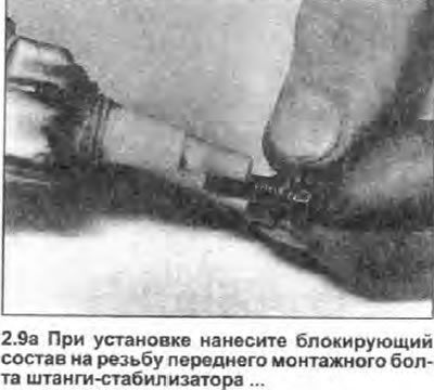
9. Install in the reverse order of removal, paying attention to the following (see photo).
- A) Apply a small amount of multipurpose grease to all linkage pivot points.
- b) Tighten all nuts and bolts securely, remembering that a blocking compound must be applied to the threads of the bolt that secures the stabilizer bar to the transmission case.
- c) Finally, check that the linkage runs smoothly without any jerks and that all rubber boots are properly seated in their respective grooves.
 |  |