
Type 002 Gearbox Cable Bracket Mounts
1 - bracket mounting bolts; 2 - bracket
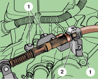
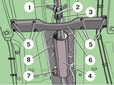
Fastening the drive cables to the gearbox
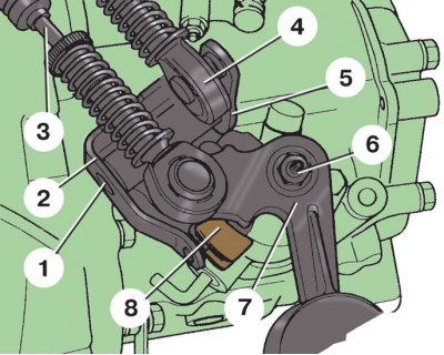
1 - axis lever; 2 - gear selection lever; 3 – a cable of inclusion of transfer; 4 – a cable of a choice of transfers; 5 - retaining ring; 6 - nut; 7 – the lever of inclusion of transfers; 8 - slider
Location of the speedometer drive speed sensor on the box type 002
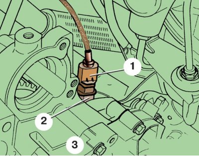
1 - connecting block; 2 – speedometer drive speed sensor; 3 - gearbox
Clutch Slave Cylinder Location
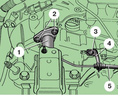
1 - working cylinder; 2 – a bolt of fastening of the cylinder; 3 – a bolt of fastening of the holder; 4 - holder; 5 – a tube of a hydraulic drive of coupling
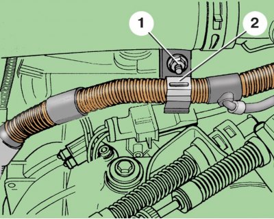
Silencer exhaust pipe coupling on models with gearbox type 002
1 – a reception pipe of the muffler; 2 - connecting sleeve; 3 - coupling bolt; 4 - resonator; 5 - nuts; 6 - cross member; 7 – resonator mounting pad; 8 - heat-insulating screen
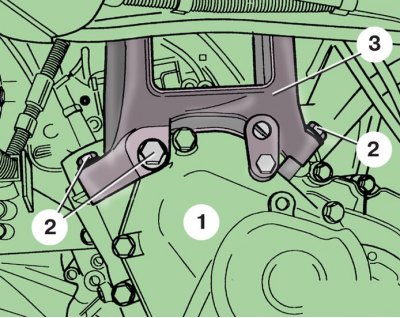
Arrangement of points of fastening of a gear box of type 002 to the engine
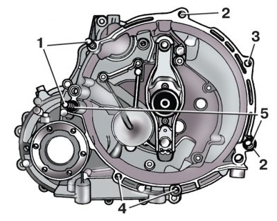
1 - studs; 2 - a hole for a stud mounted on the cylinder block; 3 – hole for M10 bolt with M8 shank; 4 - bolt holes; 5 - guide sleeve
Removing
Attention! It is necessary to remove and install the gearbox on a lift or an inspection ditch.
1. Remove the upper engine cover (see subsection 2.1).
2. Remove the air filter (see subsection 4.1).
3. Remove the battery and its holder (see subsection 10.2).
4. Disconnect a wire from the traction relay of a starter.
5. Unscrew the fastening nut 1 and remove the holder 2 from the stud. Tie it to a hose.
6. Remove the engine speed sensor.
7. Remove three screws 1 (see fig. Type 002 Gearbox Cable Bracket Mounts) fasteners and disconnect from the gearbox bracket 2 for fastening the cables of the gearbox drive.
8. Remove retaining ring 5 (see fig. Fastening the drive cables to the gearbox) axis of the gear selector lever.
9. Take out an axis 1, remove the lever 2 of a choice of transfers and put it aside together with a cable.
10. Unscrew the fastening nut 6, remove the gearshift lever 7 and set it aside along with the cable.
11. Remove the starter.
12. Disconnect block 1 (see fig. Location of the speedometer drive speed sensor on the box type 002) with wires from the sensor 2 speed drive speedometer.
13. Remove bolt 3 (see fig. Clutch Slave Cylinder Location) fasteners and disconnect the holder 4 of the hydraulic clutch tube from the gearbox.
14. Unscrew the two fastening bolts 2 and remove the slave cylinder 1 of the clutch drive from the clutch housing without disconnecting the tube 5 from it. Secure the slave cylinder with a wire so that it does not interfere with the removal of the gearbox.
Attention! After removing the slave cylinder, never depress the clutch pedal.
15. Unscrew all nuts accessible from above (see fig. Arrangement of points of fastening of a gear box of type 002 to the engine) fixing the gearbox to the engine.
16. Remove the front left wheel.
17. Remove the engine crankcase mudguard.
18. Remove the front left wheel well cover.
19. Loosen the tightening bolts 3 (see fig. Silencer exhaust pipe coupling on models with gearbox type 002) collars of fastening of the connecting plug 2, disconnect a reception pipe 1 from the resonator 4 of system of release of the fulfilled gases.
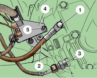
20. Having unscrewed a bolt of 1 fastening, disconnect «mass» wire 2 from gearbox (3 - reverse light switch; 4 - bracket; 5 - nut).
21. Disconnect the block with wires from the switch 3 of the reversing light.
22. Unscrew fastening nut 5 and disconnect bracket 4 from the box. Set bracket 4 with wires aside.
23. Disconnect both wheel drives from the flanges (see subsection 7.1.3.7).
24. Disconnect the ball joint from the front suspension arm (see subsection 7.2.3) and rack from the bar of the stabilizer bar (see subsection 7.2.7).
25. Pull out the telescopic column 2 (see fig. V clause 10 of subsection 7.2.3) front suspension, install a wooden spacer between it and the body 1. Suspend the wheel drive with a wire, for example, to the front suspension spring. Fasten the right wheel drive as high as possible. At the same time, be careful not to damage the lacquer coating of the axle shafts.
26. Turn away three bolts 1 and 3 fastenings and remove a back support 2 of the power unit.
27. Remove the gearbox-to-engine nut located above the right flange of the differential output shaft.
28. Hook the engine on the lifting eyes and tighten the hoist cables, taking care not to damage the hoses and wires.
29. Slightly raise the engine so as to unload the left support of the power unit, and unscrew the bolts 2 (see fig. V clause 39 of subsection 2.12.7) fixing the left support.
30. Lower the gearbox 1 so that through the niche of the front left wheel to get access to the bolts 2 of the gearbox bracket. At the same time, make sure that the gearbox does not rest on the front suspension beam. Unscrew three bolts 2 fastening the bracket 3.
31. Loosen the remaining bolts and nuts securing the gearbox to the engine (see fig. Arrangement of points of fastening of a gear box of type 002 to the engine).
32. Pull the transmission away from the engine and lower it by tilting it appropriately and pushing the engine in the opposite direction.
Installation
Install the gearbox in reverse order. When installing gearshift levers, insert slider 8 (see fig. Fastening the drive cables to the gearbox), mounted on the lever 2 of the gear selection, into engagement with the lever 7 of the gear. Check the level and add oil to the gearbox if necessary.
Tightening torques, Nm
| Bolt of fastening of an arm to a transmission | 40, turn 90° |
| Nut of fastening of the lever of inclusion of transfers | 25 |
| Bolt of fastening of cables of a drive of a gear box | 25 |
| Nuts and bolts securing the gearbox to the engine | 45 |