
Removing
1. Remove the expansion tank of the engine cooling system.
2. Remove the plastic covers of the shock absorber supports in the engine compartment.
If the cylinder head is removed from the engine
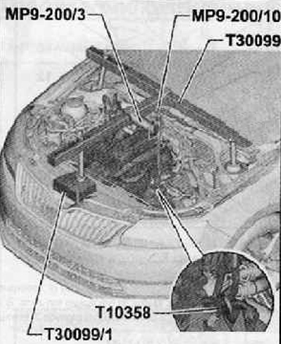
3. Position special tool -T30099- together with support bracket -MP9-200/3- above the engine compartment of the vehicle as shown in the figure below.
4. Unscrew the bolt securing the gearbox to the engine and screw in the bolt together with the mounting bracket -T10358- as shown in the figure below.
5. Hang out the power unit using the MP9-200/10 spindle.
Note. Fix the T30099 hanging tool with the support T30099/1 and block it from moving.
If the cylinder head has not been removed
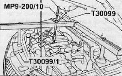
6. Install a special device for hanging the power unit T30099, together with the support T30099/1, as shown in the figure below.
7. By rotating the MP9-200/10 spindle, hang out the power unit assembly (install it with preload).
For all vehicles
8. Remove attachment drive belt (more, see relevant section in this chapter).
9. Remove the right support of the power unit assembly.
10. Remove the mounting bolts and remove the water pump drive pulley (for details, see the relevant section in chapter Cooling system).
11. Unscrew the fastening bolt and remove the attachment drive belt guide pulley assembly (only for vehicles with air conditioning).
12. Remove the attachment drive belt tensioner assembly with pulley.
13. Remove the generator assembly (for details, see the relevant section in chapter Engine electrical equipment).
14. To remove the top branch pipe of the engine cooling system in gathering.
15. Using special tool T10121, block the crankshaft from rotating. Then, unscrew the mounting bolt and press the pulley from the crankshaft shank.
16. Unscrew the mounting bolts and remove the oil pan, the oil dipstick guide pipe and the engine oil level and temperature sensor.
17. Disconnect the hose from the exhaust gas recirculation vacuum control valve.
18. Remove all bolts securing the timing chain housing to the cylinder head and cylinder block.
19. Remove the timing chain case. If necessary, apply light blows with a rubber mallet around the perimeter of the timing chain case to facilitate detachment of the case.
20. Using a special wooden scraper, remove the remaining sealant from the mating surfaces.
21. Clean and wash the mating surfaces on the timing chain housing and engine. Make sure that the mating surfaces are free of engine oil and lubricant.
Installation
Note.
- bushing (pos. 17 in the general view in the figure above) must only be installed after the timing chain housing has been installed, otherwise the O-ring may be damaged.
- Check and make sure that the oil separator was not damaged during removal.
- The timing chain housing must be installed within 5 minutes of sealant being applied to the mating surfaces.
- If there is no blue sealant in the threads of the M6 screws, replace the screws with new ones with sealant.
1. Cut off the end of the dosing tube of the sealant bottle (hole diameter should be 3mm).
2. Apply a continuous bead of sealant to the bonded surface of the timing chain housing as shown in the figure below (arrow A).
Note. Apply sealant to the junction of the cylinder head with the cylinder block, as shown in the figure below (arrow A).
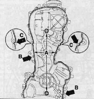
Note. Position B in the figure above indicates the installation location of the guide bush.
Note. The diameter of the sealant bead must not exceed 3 mm, otherwise excess sealant may enter the oil pan and clog the holes in the oil receiver mesh.
3. Install the timing gear target housings on the engine, gently press it down and tighten all the mounting bolts by hand.
4. Tighten all the bolts of the timing chain housing in the sequence shown in the figure below with the required tightening torque.
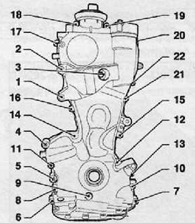
Tightening torques for the bolts of the timing chain housing:
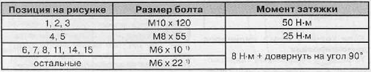
1) If there is no special blue sealant on the threaded part of the fastening bolt, the bolt must be replaced with a new one.