Contents: General appearance ⬇ Checking the piston ring clearance ⬇ Checking the piston ring clearance…⬇ Checking the piston diameter ⬇ Checking the inner diameter of the…⬇ Assembly position and piston…⬇ Position for assembling bearing…⬇
General appearance
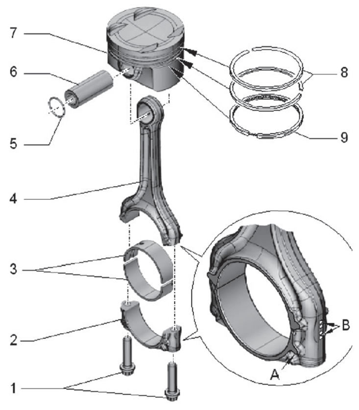
1. Connecting rod cap fastening bolts, tightening torque during installation: 30 N·m + additionally tighten by an angle of 90'2. Connecting rod cap 3. Connecting rod bearing shells 4. Connecting rod 5. Retaining ring 6. Piston pin 7. Piston 8. Compression piston rings 9. Oil scraper piston ring
Checking the piston ring clearance
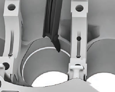
Install the ring perpendicularly from the top down to the bottom of the bore in the cylinder at a distance of approximately 15 mm from the edge of the cylinder, as shown in the figure below. For installation, use a piston without rings.
| Piston ring(dimensions in mm) | new | Wear limit |
| Compression rings | 0,20+°15 | 0,7 |
| Oil scraper ring rack (two elements) | 0,50+°20 | 1,0 |
| Oil scraper ring rack (three elements) | 0,20+0,20 | 1,2 |
Checking the piston ring clearance by height
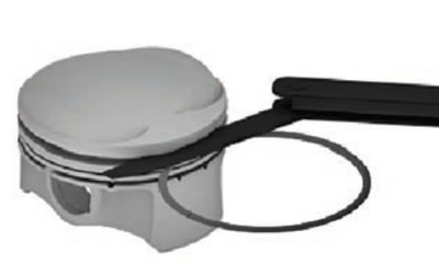
Before proceeding with the inspection, clean the piston ring grooves.
| Piston ring(dimensions in mm) | New | Wear limit | |
| 1st compression ring (federal Mogul ring manufacturer) | 0.05-0.09 | 0,15 | |
| 1st compression ring (mahle ring manufacturer) | 0.035 -0.085 | 0,15 | |
| 2nd compression ring | 0.03-0.07 | 0,15 | |
| Part 2 of the oil scraper rack | Not measured | ||
| 3rd part of the oil scraper rack | 0.04-0.08 | - | |
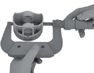
Checking the piston diameter
- Measure at a distance of 15 mm from the bottom edge, perpendicular to the axis of the piston pin. Maximum deviation from the nominal size: 0.04 mm.
Nominal piston diameter: 74.42 mm
Dimensions include special coating for transportation. Coating thickness: 0.015 mm.
Checking the inner diameter of the cylinders
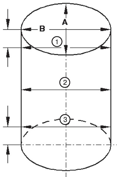
- Measure the cylinder crosswise at 3 places in the transverse direction (A) and in the longitudinal direction (B), as shown in the figure below. Maximum deviation from the nominal size: 0.08 mm.
Nominal cylinder bore: 74.5 + 0.015 mm.
Assembly position and piston attachment to cylinder liners
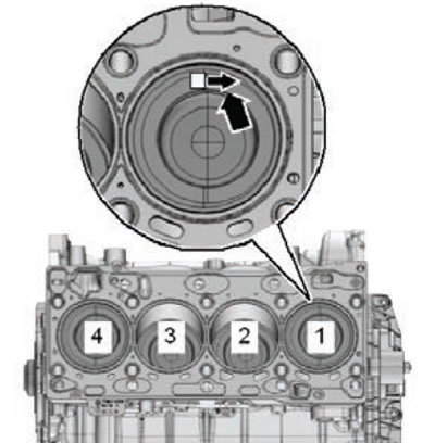
The arrow on the piston bottom (arrows) should point towards the pulley.
Position for assembling bearing shells in connecting rods
- Place the bearing shells into the middle of the connecting rod or connecting rod bearing cap.
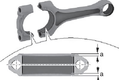
Size (a) = 2.5 mm.