



Contents: Removal and installation ⬇ Installation ⬇
Removal and installation
Removal the belt from the camshaft pulleys
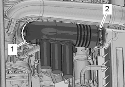
1. Loosen the mounting clamps (1) and (2).
2. Disconnect the air duct pipes of the intake system as shown in the figure below.
3. Release the air hoses from the clamps on the air duct pipe.
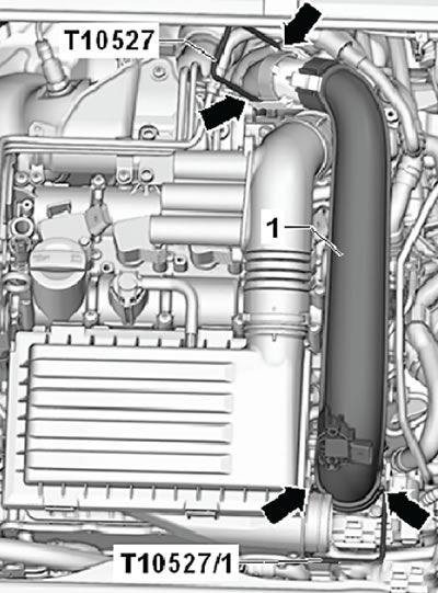
4. Unlock the latches (arrows) using the special tool (T10527) and remove the air duct pipe assembly as shown in the figure below.
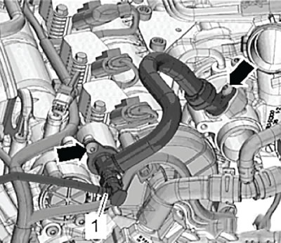
5. Press the release buttons and disconnect the hose (1) for the activated carbon filter, as shown in the figure below.
6. Unscrew the fastening screws (arrows) and disconnect the crankcase ventilation hose shown in the figure below.
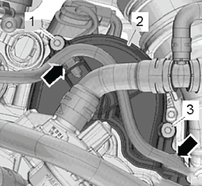
7. Release the wiring harness (arrows) from the posts on the cover as shown in the figure below.
8. Unscrew the mounting screws (1) and (3) and remove the cover (2) for the toothed pulley of the water pump of the cooling system, as shown in the figure below.
9. Unscrew the fastening screws (arrows) and remove the cover (1) shown in the figure below.
10. Drain the coolant into a pre-prepared container (for more details, see the relevant section in the chapter "Cooling system").
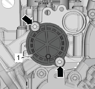
11. Unscrew the fastening screw (2) shown in the figure below.
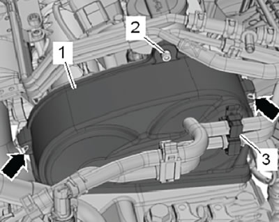
12. Loosen the fastening clamps (arrows), then remove the upper timing belt cover (1), as shown in the figure below.
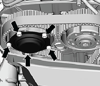
13. Unscrew the mounting screws (arrows) shown in the figure below, then remove the exhaust camshaft phase shifter cover.
Caution: Wrap the timing belt with a rag before removing the phase shifter cover to prevent engine oil from getting on the belt.
14. Drain the coolant into a pre-prepared container.
15. Unscrew the mounting screws and remove the thermostat housing cover.
16. Remove the lower engine compartment protection.
17. Turn the crankshaft to set the piston to TDC.
- Unscrew the plug from the hole for fixing the crankshaft in the TDC position of the piston of the first cylinder.
- Screw the locking bolt (T10340) into the hole in the cylinder block until it stops, and then tighten it to a tightening torque of 30 N·m.
- Turn the crankshaft in the direction of its working rotation until it stops.
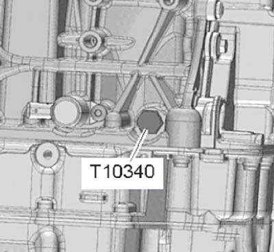
Note: The crankshaft is locked only with a special bolt and when rotating in the direction of its working rotation.
Attention:
If the lock bolt is not screwed in all the way, the crankshaft will not be positioned correctly. In this case it is necessary:
- Unscrew the lock bolt.
- Turn the crankshaft 90° in the direction of its working rotation.
- Screw the locking bolt into the cylinder block until it stops and tighten it to a tightening torque of 30 Nm.
- Turn the crankshaft again in the direction of working rotation until it stops.
- On both camshafts on the gearbox side, the notches (arrows) should not be at the highest points, as shown in the figure below.
- On the exhaust camshaft (A), samples (top arrows) should be visible through the cutouts in the toothed pulley as shown in the figure below.
- On the intake camshaft (E) samples (bottom arrows) must be above the horizontal center axis of the camshaft as shown in the figure below.
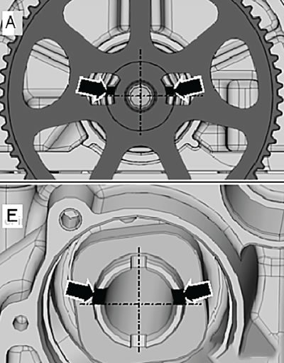
- If the camshafts are installed differently, it is necessary to unscrew the lock bolt and turn the crankshaft one revolution. Then block it again.
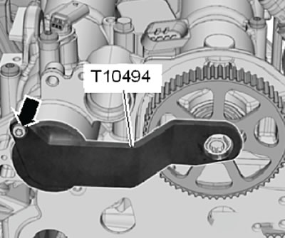
Note: The special locking tool (T10494) should fit onto the camshafts without difficulty.
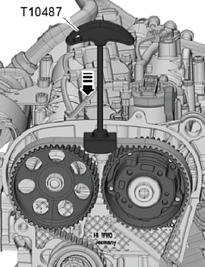
18. Using the special tool (T10487), press in the direction of the arrow on the timing belt, as shown in the figure below.
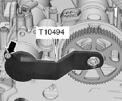
19. Install the special locking tool (T10494) onto the camshafts until it stops, then hand-tighten the mounting bolt (arrow), shown in the figure below.
Caution: Do not use the T10494 camshaft locking tool as a counter-support when removing the camshaft timing pulley bolts.
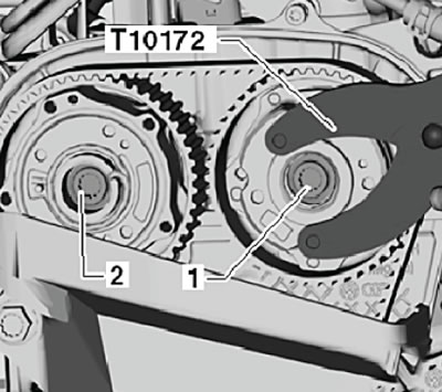
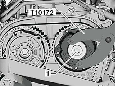
20. Install the counter support (T10172) with the adapter (T10172/1) to unscrew the locking bolt (1) of the camshaft drive toothed pulley, as shown in the figure below.
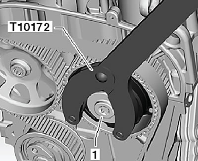
21. Unscrew the mounting bolts (1) and (2), each by one turn. To do this, use a special counter support (T10172) with adapters (T10172/2) and (T10172/1).
Caution: If the timing belt is to be reused, an arrow indicating the direction of rotation must be applied to its surface before removal.
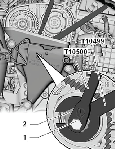
22. Unscrew the mounting bolt (1) shown in the figure below using the special tool (T10500).
23. Using a special key (T10499), move the eccentric of the timing belt tensioner roller (2) as shown in the figure below.
24. Remove the timing belt from the camshaft toothed pulleys.
Installation
Note:
- Replace all mounting bolts that require additional tightening at a certain angle when tightened.
- After disassembly, it is always necessary to replace the sealing rings and self-locking nuts and mounting bolts.
1. Check that the crankshaft and camshafts are correctly installed at TDC. To do this, install a special locking device (T10494) on the camshaft housing, as shown in the figure below.
Attention:
- Do not use a special camshaft locking tool as a counter-support when tightening the mounting bolts.
- The lock bolt (T10340) must be tightened until it stops against the cylinder block and then tightened to a tightening torque of 30 Nm.
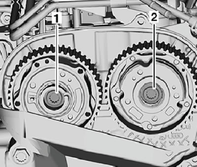
2. Install new camshaft drive pulley mounting bolts and tighten them slightly (1) and (2). The camshaft pulleys should be able to rotate relative to the shafts, but not become warped.
(Information presented on the website: skodabook.ru)
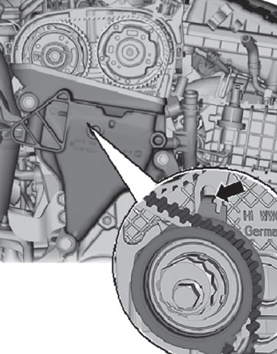
- The metal tab (arrow) on the timing belt tensioner roller must be positioned opposite the recess in the cylinder head as shown in the figure below.
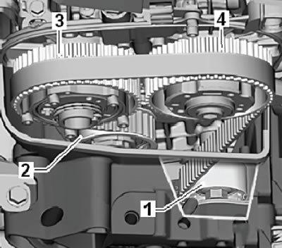
3. Place the timing belt first on the tensioner roller (2), then on the camshaft toothed pulleys (3) and (4), and then on the guide roller (1), as shown in the figure below.
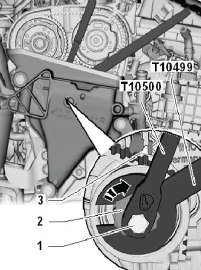
4. Turn the eccentric (2) of the timing belt tensioner roller using the special key (T10499) in the direction of the arrow and set it so that the pointer (3) is located 10 mm to the right of the adjustment window, as shown in the figure below.
5. Move the tensioner roller eccentric back and set it so that the pointer is opposite the adjustment window.
Please note: Use a torque wrench (VAS 6583) to tighten the mounting bolts.
6. While holding the tensioner eccentric in this position, tighten the mounting bolt (1) to a tightening torque of 25 Nm. To perform this operation, use the special tool T10500 together with the torque wrench VAS 6583.
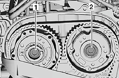
7. Using the counter support (T10172) together with the adapter (T10172/1) and (T10172/2), tighten the camshaft drive toothed pulley mounting bolts (1) and (2) with a tightening torque of 50 N·m.
8. Unscrew the crankshaft lock bolt (T10340) from the cylinder block.
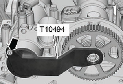
9. Unscrew the mounting bolt (arrow) and remove the camshaft lock (T10494), shown in the figure below.
10. Perform a valve timing check.
11. Unscrew the crankshaft lock bolt from the cylinder block.
12. Unscrew the mounting bolt and remove the camshaft lock.
13. Finally tighten the camshaft drive toothed pulley mounting bolts by turning them to an angle of 135°.
14. Install and tighten the lock bolt (1) to a tightening torque of 20 Nm, as shown in the figure below. To perform this operation, it is necessary to use a counter support (T10172) and an adapter (T10172/1).
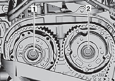
15. Install and tighten the lock bolt (1) shown in the figure below.
16. Further installation is carried out in the reverse order of removal.