
Removing
1. Remove the top decorative engine cover.
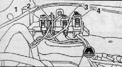
2. Disconnect the wiring harness connectors described below.
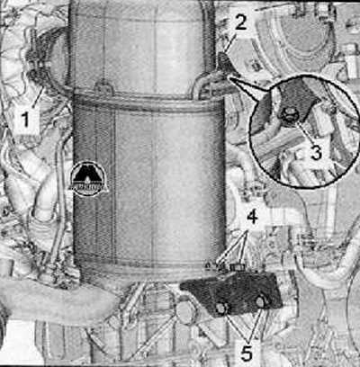
- (1): Disconnect connector from wiring harness for exhaust gas temperature sender 1 -G235-.
- (2): Disconnect connector from wiring harness for exhaust gas temperature sender 3 -G495-.
- (3): Disconnect connector from wiring harness for exhaust gas temperature sender 4 -G648-.
- (4): Disconnect connector for lambda probe wiring harness -G39- as shown in figure below.
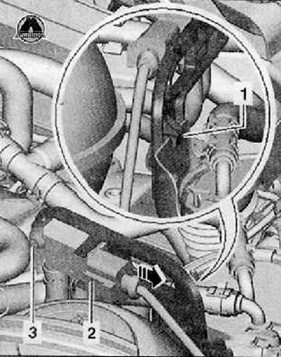
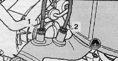
3. Unplug electrical harness connector at differential pressure sender -G505- (2), as shown in the figure below.
4. Unscrew the fastening screw (3) and remove differential pressure sender -G505- shown in figure below.
5. Remove the wires from the holders on the motor and the thermal insulation cover of the particle filter, if necessary, remove the installed cable clamps.
6. Remove lambda probe -G39- with lambda probe spanner.
7. Remove with a set of keys (Т10395) Exhaust gas temperature sender 3 -G495- shown in the figure below.
8. Remove the mounting bracket (1) between the particulate filter and the turbocharger, as shown in the figure below.
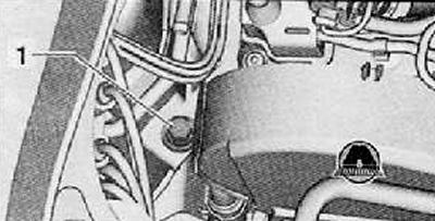
9. Unscrew the fastening screw (1), shown in the figure below.
10. Remove the bottom protective cover of the engine compartment.
11. Unscrew the fastening screws (1) right drive shaft guard, if fitted.
12. Set the front suspension subframe to the service position (for details, see the relevant section in chapter Chassis).
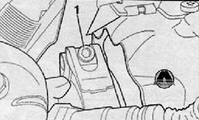
13. Unscrew exhaust gas temperature sender 4 -G648- (1) from the exhaust pipe behind the particulate filter.
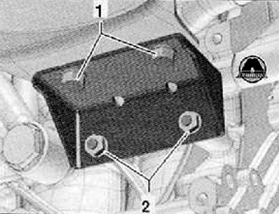
14. Unscrew the fastening screws (1) and mounting nuts (2), shown in the figure below.
15. Remove the particulate filter holder.
Note.
- The assistance of a 2nd mechanic is required to remove the particulate filter.
- The connector in the front of the exhaust pipe must not be angled more than 10°- risk of damage.
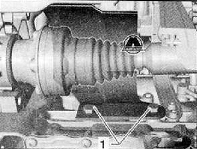
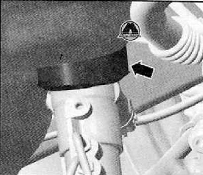
Note. The connecting piece must be secured against excessive tension with the transport device -T10403- (arrow), as shown in the figure below.
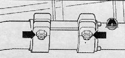
16. Unscrew the fastening nuts (arrows) double clamp, and then pull it back from the front of the exhaust pipe.
17. Carefully remove front section of exhaust pipe with particle filter above loosened front suspension subframe together with differential pressure sender -G505-.
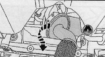
18. The particle filter should be rotated 180°and removed as shown in the figure below.
Installation
1. Installation is made in reverse order to removal. Observe the conditions below.
Note.
- Before proceeding with the installation of the axle suspension mounting beam with the steering gear housing, it must be ensured that the seal on the steering gear housing rests without folds on the mounting plate. This will properly seal the opening leading to the footwell, otherwise water or noise may enter.
- Replace seals, self-locking nuts and particle filter bracket. All cable clamps that loosen during removal must be reattached in the same place when reinstalled.
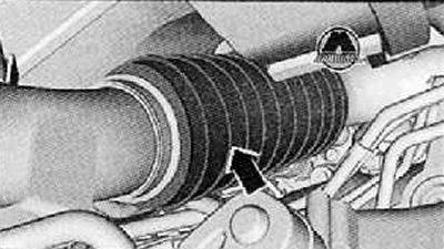
Respect the installation position of the seal (arrow) (control groove).
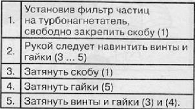
Follow the sequence of operations when installing the particle filter.
 |  |
Assemble the exhaust system so that it is stress-free.