



Contents: Removal ⬇ Installation ⬇
Removal
1. Remove the camshaft covers.
2. Remove the ignition coil of the 1st cylinder.
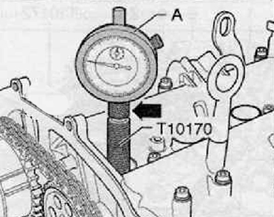
3. Screw the T10170 dial indicator adapter into the spark plug hole until it stops, as shown in the figure below.
4. Install the dial indicator (A) with the extension "T10170/1" until it stops, clamp it with the clamping nut (arrow), as shown in the figure below.
5. Turn the crankshaft in the direction of engine shaft rotation until the piston of the 1st cylinder is at TDC. Mark the position on the deviation indicator using a small arrow.
Note.
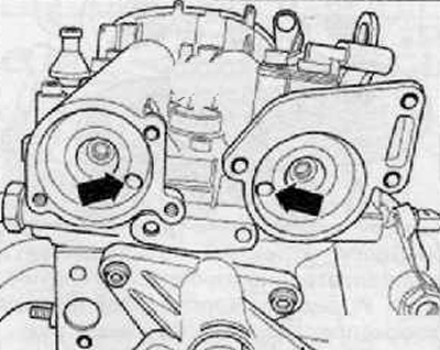
- The holes (arrows) in the camshafts must be in the position shown in the figure. If necessary, turn the crankshaft one revolution (360°).
- If the crankshaft turns more than 0.01 mm past TDC, then turn the crankshaft back approximately 45°. Then turn it in the direction of engine shaft rotation to the TDC position of the 1st cylinder.
- Permissible deviation from TDC of piston of the 1st cylinder:±0.01 mm.
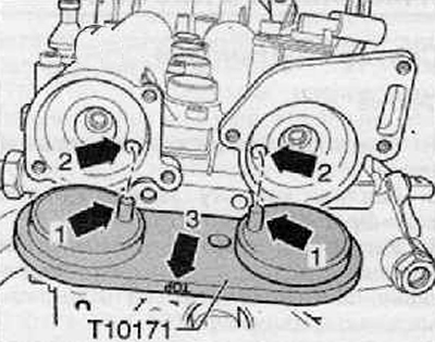
6. Insert the camshaft locking tool "T10171" or "T10171A" into the holes in the camshafts until it stops. The locking mandrels (arrows 1) must enter the holes (arrows 2) as shown in the figure below. The inscription "TOP" "arrow 3" must be legible from above.
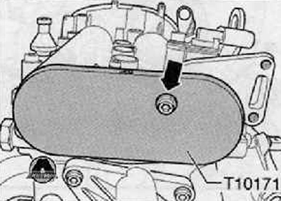
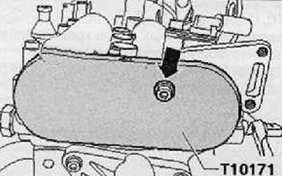
7. To fix the locking tool for camshafts "T10171" or "T10171A", manually screw in the M6 screw (arrow), shown in the figure below; without tightening it further.
8. Remove the timing chain housing.
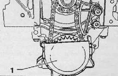
9. Remove the cover (1) from the oil pump chain sprocket as shown in the figure below.
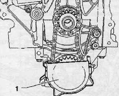
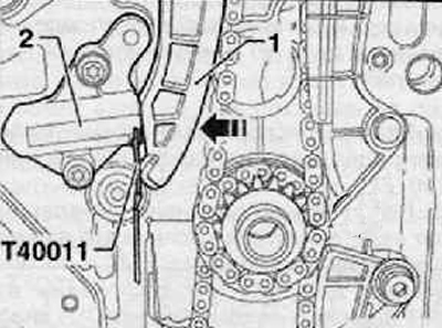
10. Press the tension bar by hand in the direction of the arrow and use the locking mandrel "T40011" to lock the plunger of the chain tensioner.
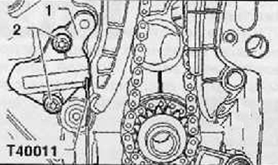
11. Remove the chain tensioner (2) shown in the figure below.
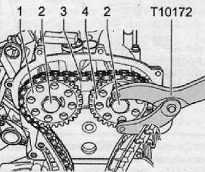
12. Using a suitable felt-tip pen, mark the direction of movement of the camshaft drive chain (3).
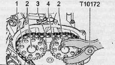
13. Unscrew the mounting bolts (2), remove the sprocket of the camshaft chain drive, which drives the intake valves (1), with the camshaft drive chain (3), as shown in the figure below. Use the counter support "T10172" for this.
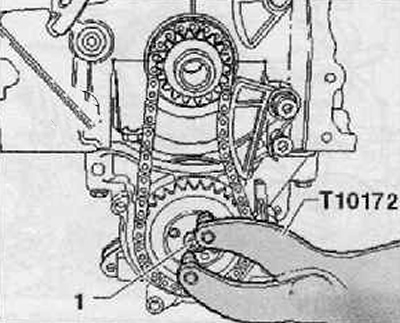
14. Use the counter support "T10172" to hold the oil pump chain sprocket and loosen the mounting bolt (1), shown in the figure below.
15. Using a lever-like motion of the screwdriver, release the tension spring (1) on the screw (2) and remove the tension spring (1), as shown in the figure below.
16. Unscrew the mounting bolt (3), remove the oil pump drive chain tensioner.
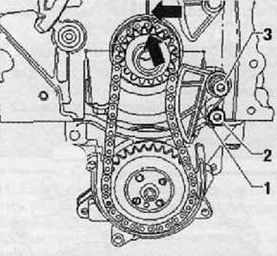
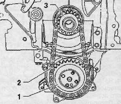
17. Using a suitable felt-tip pen, mark the direction of movement of the oil pump drive chain (2).
18. Unscrew the chain drive sprocket mounting bolt (1), remove the chain drive sprockets (1) and (3) together with the oil pump drive chain (2), as shown in the figure below.
Installation
Note: The crankshaft must be in the TDC position of the piston of the 1st cylinder.
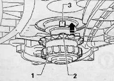
1. Install the chain sprocket (1) in the direction of the arrow onto the crankshaft journal until it stops, as shown in the figure below.
Caution: The projection (2) on the chain sprocket (1) must be in the spline (3) of the crankshaft journal, as shown in the figure below.
2. Use a felt-tip pen to mark the positions of the chain drive pinion and crankshaft in relation to the cylinder block.
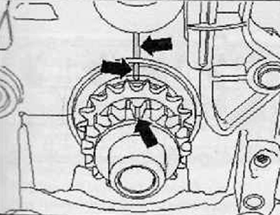
3. Install the oil pump drive chain (3) onto the chain sprocket (1) as shown in the figure below.
4. After inserting the oil pump chain drive sprocket (2) into the oil pump drive chain (3), place it on the oil pump drive shaft
Note.
- Pay attention to the marked direction of rotation on the drive end of the oil pump.
- The oil pump chain sprocket can only be installed on the oil pump drive shaft (arrow) in one single position.
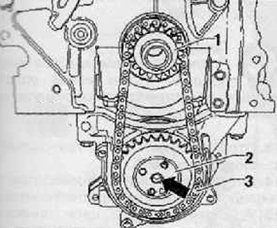
5. Hold the oil pump chain sprocket with the T10172 counter support.
6. Tighten the mounting bolt (1) to a tightening torque of 20 Nm + an additional ¼ turn 90°, as shown in the figure below.
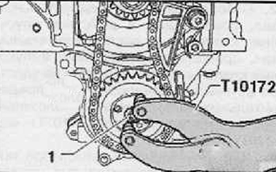
7. Install the chain tensioner on the oil pump drive chain, tighten the fastening screw (3) with a torque of 15 Nm.
8. Using a screwdriver, install the tension spring (1) onto the screw (2) as shown in the figure below.
Note.
- Pay attention to markings (arrows).
- The crankshaft must not be allowed to turn.
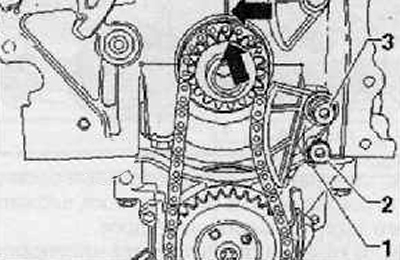
9. Install and tighten by hand, preliminarily. the camshaft chain sprocket mounting bolt (3), as shown in the figure below.
10. Place the camshaft drive chain (1) on the crankshaft chain sprocket (4), on the exhaust camshaft sprocket (3) and screw on the intake camshaft drive sprocket (2) with a new mounting bolt, as shown in the figure below.
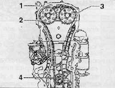
11. The camshaft drive chain must fit against the guide bar (1) and the crankshaft chain sprocket (arrow), as shown in the figure below.
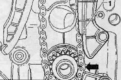
12. Install the chain tensioner (1), tighten the fastening screws (2) with a torque of 9 Nm.
13. Tighten the camshaft drive chain by removing the locking tool "T40011" from the tensioner housing.
14. Check the markings on the crankshaft chain drive sprocket and on the cylinder block: they should be opposite each other.
15. Tighten the mounting bolt (2) with a torque of 40 Nm and the bolt (4) with a torque of 50 Nm (use the counter support "T10172").
Note: After checking the valve timing, it is necessary to tighten the mounting bolts (2) and (4) by an angle of 90°.
16. Unscrew the screw (arrow), remove the locking tool for camshafts "T10171" or "T10171A" from the camshaft housing, as shown in the figure below.
17. Check the installation of the valve timing mechanism.
18. Install the oil pump gear housing (1) shown in the figure below.
19. Install the timing chain housing.
20. Further installation is carried out in the reverse order of removal.