
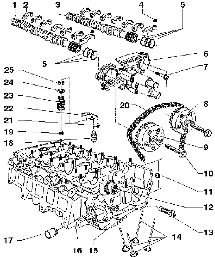
11.1a Timing parts
1 Intake camshaft
2 Camshaft covers
3 Exhaust camshaft
4 Nut, 5 Nm, then tighten to 45°
5 O-rings, in case of leakage, the entire set is replaced, when installing the body 6, lubricate the mating surfaces of the O-rings, do not overstretch the rings when replacing
6 Timing timing housing
7 Bolt, 8 Nm, installed on the fixing sealant D000 600A2
8 Shaft phase adjuster 3, marked "32A"
9 Shaft phase adjuster 1, marked "24E"
10 Bolt, to be replaced, 60 Nm, then retighten 90'; when tightening, the mating surfaces of the regulator and the bolt must be dry
11 Cylinder head height (a - not less than 139.9 mm)
12 Injection pump drive sprocket
13 Shaft-bearing, lubricate before assembly
14 Valves, processing (except for lapping) not allowed; graduation - with sodium filling
15 Centering sleeve
16 Cylinder head
17 Pusher injection pump
18 Valve clearance hydraulic compensator
19 Oil cap
20 Timing chain
21 Retainer
22 Rocker
23 Valve spring
24 Valve spring plate
25 Split valve lock crackers
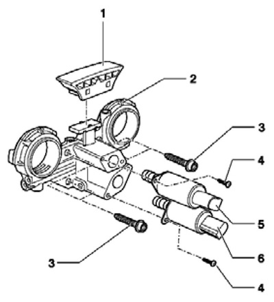
11.1b Installation details of the timing case
1 Chain guide, fixed to housing 2
2 Timing adjuster housing, lubricate the mating surfaces of the O-rings before installation
3 Bolt, 8 Nm, installed on the fixing sealant D000 600A2
4 Bolt, 3.8 Nm
5 Valve No. 1 for adjusting the phases of the intake shaft ("N205")
6 Valve No. 1 for adjusting the phases of the exhaust shaft ("N318")
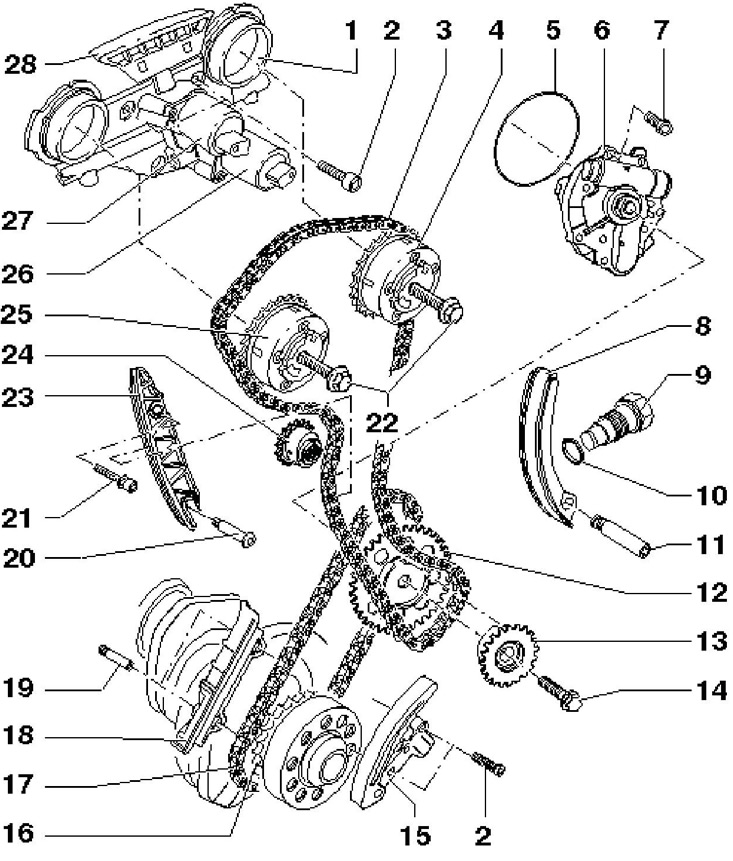
11.1c Timing drive and oil pump installation details
1 Timing timing housing
2 Bolt, 8 Nm, screwed in with fixing sealant D000 600A2
3 Timing chain
4 Exhaust shaft phase adjuster
5 O-ring, to be replaced
6 Oil pump
7 Bolt, 8 Nm, to be replaced
8 Chain tensioner 3
9 Chain tensioner 3.50 Nm, crank the engine only with the tensioner installed
10 O-ring
11 Axial bolt of the rail 8, 10 Nm
12 Chain sprocket 17
13 Chain sprocket 3
14 Bolt class 10.9, to be replaced, 60 Nm, then retighten by 90°
15 Tensioner (with strap) chains 17; crank the engine only with the tensioner installed
16 Crankshaft sprocket
17 Oil pump drive chain
18 Chain guide 17
19 Bolt without bushing, for rail 18, 10 Nm
20 Bolt, 10 Nm
21 Bolt, 23 Nm
22 Bolt, to be replaced, 60 Nm, then retighten 90', mating surfaces must be dry when tightening
23 Chain guide 3
24 Injection pump drive sprocket
25 Inlet shaft phase adjuster
26 Valve No. 1 for adjusting the phases of the exhaust shaft ("N318")
27 Valve No. 1 for adjusting the phases of the intake shaft ("N205")
28 Chain guide 3, fixed to housing 1
Removal of camshafts, timing regulators and drive chains
2. Remove air duct and air cleaner with connecting hose going to throttle assembly (see chapter 4).
3. Remove the upper part of the inlet pipeline (see chapter 4).
4. Remove the cylinder head cover (see Section 9).
5. Remember or mark the electrical wiring connection points and disconnect the connectors indicated in illustration 9.25. Release the wiring.
6. Remove the vacuum pump (see Section 9).
7. Give the fasteners of the upper and lower coolant pipes on the upper cover of the timing chain, and then remove the bolts (see illustration 9.31) and remove the top cover. Cover the opening of the lower timing chain cover with a clean cloth so that no parts fall into it.
8. Turn the crankshaft with support T10172 clockwise until the TDC marks are aligned (see illustration 9.29a) and insert template T10068A into the slots in both camshafts (see illustration 9.45).
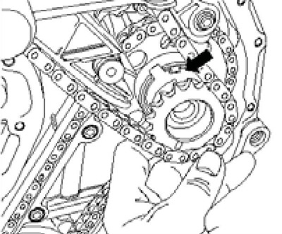
9. Fix the position of the injection pump drive sprocket with tool T10363 (see resist. illustration). At the same time, the label (A) on the hub of the injection pump should point upwards.
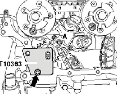
11.9 Fixing the position of the injection pump drive sprocket
Note: If the vacuum pump drive stud is not vertical, remove template T10068A and rotate the crankshaft until the stud is vertical and the template can be installed.
10. Turn out the timing chain tensioner (see illustration 9.30).
11. When tightening/loosening the timing adjusters, hold the camshafts with an open end wrench SW27 (see illustration 9.32), while template T10068A should not be installed.
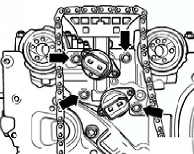
12. Turn out bolts (1 and 2 in Illustration 9.33) securing the timing adjusters and remove both adjusters.
13. Remove 4 bolts (1 in Figure 9.35) from the timing case (2) and remove it from the shafts in the direction of the arrow.
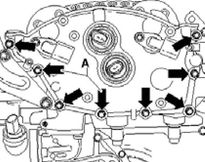
14. For intake shaft (And on the opposite illustrations) remove its covers in the sequence 1-13-3-11-7, and then loosen the cover bolts No. 5 and No. 9 in a cross order and remove them. for exhaust shaft (IN) remove its covers in the sequence 2-14-4-12-8, and then loosen the bolts securing the covers No. 6 and No. 10 in a cross order and remove them.
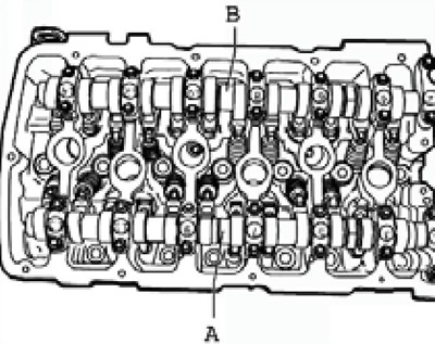
11.14 Inlet (A) and graduation (IN) camshafts and their covers
15. Gently lift the camshafts and set them aside on a clean surface. Remove the rocker arms together with the hydraulic lifters and lay them on a clean surface so that they can then be installed in their original places.
Installation of camshafts
16. Apply to the mating surfaces of #7 and #8 caps (see resist. illustration) lubricant paste G052 723A2.
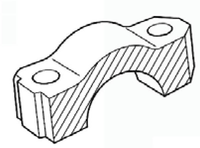
11.16 Camshaft cover mating surface
17. Make sure that all rocker arms are correctly positioned at the ends of the valves and fixed to the hydraulic lifters. Lubricate the mating surfaces of the camshafts and fit them into the cylinder head. The shafts can be identified by the marks between the pairs of cams for 4 and 5 cylinders: the exhaust shaft is marked "OZN 101", and on the inlet - "OZN 102". The camshaft lobes for cylinder #1 must face each other (see illustration 9.29b).
18. Install the camshaft bearing caps so that their protrusions (And on the opposite illustrations) were turned outward. for intake shaft (And in illustration 11.14) tighten the bolts securing its covers No. 5 and No. 9 in a cross order with a force of 5 Nm, and then tighten them at an angle of 45°. Then tighten the cap fasteners 1-13-7-3-11 in the same way. for exhaust shaft (IN) tighten the bolts securing its covers No. 6 and No. 14 in a cross order with a force of 5 Nm, and then tighten them at an angle of 45°. Then tighten the cap fasteners 2-14-8-4-12 in the same way.
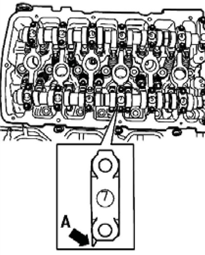
11.18 Mounting position of the camshaft cover
19. Insert template T10068A into the slots in both camshafts (see illustration 9.45).
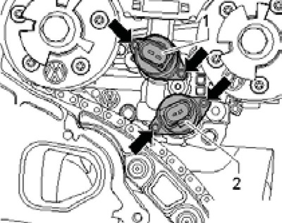
20. Unhook the oil pickup (2 to resist. illustrations) from the back of the case (1) timing adjustment and remove any dirt. Install the oil pickup in place. Lubricate the camshaft seals. Lubricate the O-ring mating surface in the timing housing and slowly slide the housing through the O-rings into position.
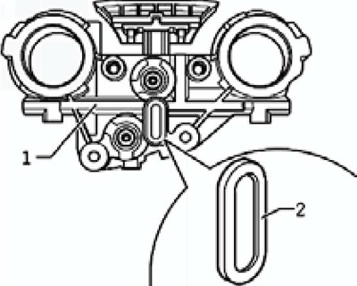
11.20 Oil intake for timing case
21. Apply to bolts (see resist. illustration) fixing sealant D000 600A2 and tighten them with a force of 8 Nm.
11.21 Bolts of fastening of the case of adjustment of phases of GRM
22. Install timing adjusters with timing chain (see subsection below).
23. Clean the mating surfaces on the top timing chain cover and on the cylinder head of old sealant with an appropriate chemical. If necessary, replace the O-rings in the upper timing chain cover.
Note: Install new O-rings without lubrication.
Degrease the indicated mating surfaces, apply sealant D176 501A1 to the upper chain cover, install the cover immediately, tighten all bolts (see illustration 9.31) its fasteners by hand, and then tighten with a force of 8 Nm.
24. Tighten the timing chain tensioner to 50 Nm.
25. Install vacuum pump and cylinder head cover (see Section 9).
26. Install the upper part of the inlet pipeline (see chapter 4).
Installation of camshaft adjusters and timing chain
27. Turn the crankshaft with support T10172 clockwise until the TDC marks are aligned (see illustration 9.29a). In this case, the camshaft cams for cylinder No. 1 must face each other (see illustration 9.29b).
28. Insert template T10068A into the slots in both camshafts (see illustration 9.45).
29. Fix the position of the injection pump drive sprocket with tool T10363 (see illustration 11.9). At the same time, the label (A) on the hub of the injection pump should point upwards.
30. Thanks to the presence of pins (see resist. illustration), the adjusters can only be mounted on the shafts in one position.
11.30 Centering pins of camshaft adjusters
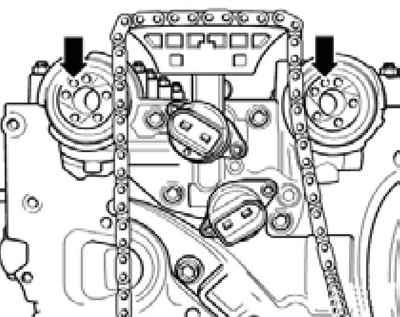
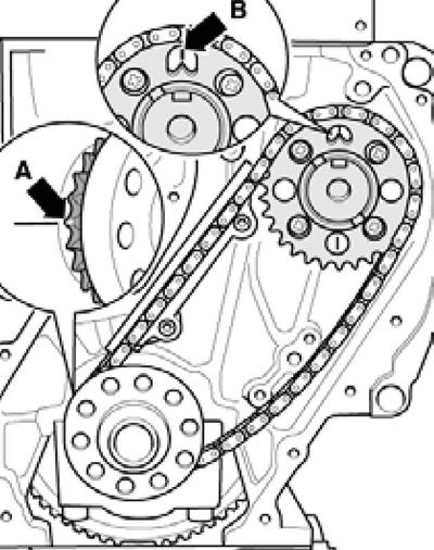
31. First install the intake camshaft timing adjuster with the timing chain on it. The timing chain to the injection pump drive gear must not sag; when the timing chain is under tension, the adjuster should be easy to install and tighten by hand. Arrow on the regulator "24E" must be aligned with the right notch on the timing case (see illustrations 10.5a-b)
32. Count 16 timing chain rollers to the right, starting from the sprocket tooth, which is opposite the arrow "24E", and mark the 16th clip with a colored pencil (see illustration 10.6).
33. Timing adjusters locked at rest, i.e. when installing the timing phases, the rotor does not turn. If the controls are not locked, turn them in both directions until they lock into place. If you cannot fix the regulators, replace them.
34. Connect the regulator "32A" with a timing chain so that the previously counted 16 rollers are located between the arrows "24E" And "32A" regulators. Install regulator "32A" with timing chain on the exhaust shaft. Arrow "32A'' on the regulator must be aligned with the right risk on the timing case (see illustrations 10.5a-b). In this case, the regulator should be easily installed and tightened by hand.
Note: A slight deviation of the arrow on the regulator from the notch on the body is allowed.
35. Remove tools T10363 and T10068A. Tighten the timing chain tensioner to 50 Nm.
36. Turn the crankshaft 2 turns and make sure that the arrows on the regulators match the risks on the timing case (see illustrations 10.5a-b).
37. Holding the corresponding camshaft by the flats with an open end wrench (see illustration 9.32) Tighten the new adjuster bolts to 60 Nm and then retighten them by 90°.
38. Install the lower timing chain cover (see Section 8).
Installing the Timing Chain and Crankshaft Chain (oil pump drive)
39. Installation is carried out with the following parts removed: flywheel, engine oil pan, lower timing chain cover and cylinder head. Depending on the degree of disassembly of the engine. adjustment can start from the corresponding position. The oil pan is installed only after installing the lower timing chain cover.
40. Set the crankshaft to the TDC position of piston No. 1. At the same time, the beveled tooth of the crankshaft sprocket (see resist. illustration) must be at the joint level. Tighten both guide rail axial bolts to 10 Nm and slide the rail over them.
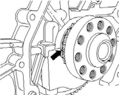
11.40 TDC position
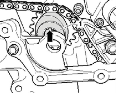
41. Install the shaft (1 per resist. illustrations) oil pump so that the flat (arrow) was located horizontally and was opposite the mark (2). Lay the crankshaft chain on the guide and place it on the crankshaft. Install the used chain so that the direction of its movement is the same.
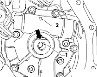
11.41 Oil pump shaft position
42. Insert a large sprocket into the chain so that the mark on the sprocket is opposite the mark located behind on the cylinder block (arrow B on resist. illustrations). Install the sprocket on the oil pump shaft. If the sprocket cannot be installed, rotate the oil pump slightly. Make sure the beveled tooth (A) coincides with the joint, and the mark on the asterisk is opposite the mark (IN) on the cylinder block.
11.42 Crankshaft chain alignment marks
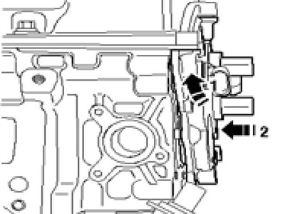
43. Install the crankshaft chain tensioner. To do this, first loosen the locking tooth in the tensioner with a small screwdriver and press the bar away from the tensioner (see resist. illustration). Then install the tensioner with the bar pressed out and tighten the bolts (see illustration 13.13) fastening it with a force of 8 Nm.

11.43 Pressing the strap from the tensioner
44. If the cylinder head is dreaming, install it. Insert template T10068A into the slots in both camshafts (see illustration 9.45). Pass the timing chain from above through the opening in the cylinder head or in the cylinder head gasket. Insert the small sprocket with the chain mounted on it into the cutout (see resist. illustration) and tighten the sprocket fasteners by hand.
11.44 Setting the small sprocket
45. Holding the crankshaft from turning with counterhold T10172 (see illustration 7.4). tighten the new bolts of both sprockets on the oil pump shaft with a force of 60 Nm, and then tighten to an angle of 90°.
Note: Only use a bolt of property class 10.9. Insert guide (2 to resist. illustrations) through the opening in the cylinder head and tighten its bolts (1 and 3). Insert guide (4) and tighten the bolt (5).
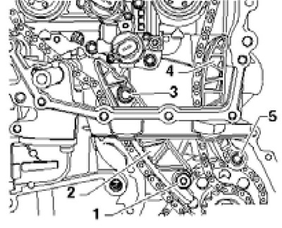
11.45 Fasteners for timing chain guides
46. Insert an asterisk (1 per resist. illustrations) high-pressure fuel pump drive together with a groove put on it by a chain (arrow) up. Make sure the chain is tight on the sprocket.
11.46 Installation of injection pump sprocket
47. Lubricate the vacuum pump shaft (4 in illustration 9.33) with clean engine oil and slide it in with the bushing (5).
48. Fix the position of the injection pump drive sprocket with tool T10363 (see resist. illustration). At the same time, the label (A) on the hub of the injection pump should point upwards.
49. Install the camshaft adjusters (see subsection above).
Removal / installation of valves for adjusting the phases of the timing
50. Remove the air duct and air cleaner (see chapter 4).
51. Remember or mark the electrical wiring connection points and disconnect the connectors indicated in illustration 9.25. Release the wiring.
52. Remove the vacuum pump (see Section 9).
53. Completely unscrew the three extreme bolts of the cylinder head cover (12-14 in illustration 9.6).
54. Give the fasteners of the upper and lower coolant pipes on the upper cover of the timing chain.
55. Hand over the fasteners (arrows on resist. illustrations) and remove the top timing chain cover. Cover the opening of the lower timing chain cover with a clean cloth so that no parts fall into it.
11.55 Fasteners for the upper cover of the timing chain
56. Remove the bolts (see resist. illustration) valve fasteners 5 turns, pull out the valves to the bolts, then completely unscrew the bolts and remove the valves. Do not subject valves to vibration.
11.56 Bolts of fastening of valves of adjustment of phases of GRM
57. Make sure that there are no scratches or dirt on the valves and their seating surfaces in the timing case. Install the valves into the body, pressing them evenly by hand until they stop. Tighten the valve mounting bolts to 3.8 Nm.
58. Clean the sealing surfaces of the upper timing chain cover and cylinder head of old sealing materials with a suitable chemical agent. If necessary, replace the O-rings in the upper timing chain cover.
59. Make sure the gasket (arrows on resist. illustrations) fits correctly on the cylinder head cover. If necessary, remove any remaining sealant at the points (A). Remove grease from mating surfaces. Apply a thin bead of D176 501A1 sealant to the clean mating surface of the timing chain top cover.
11.59 Cylinder head cover gasket
60. Apply a little sealant D454 300A2 to the places indicated in illustration 9.7 of the upper cover of the timing chain.
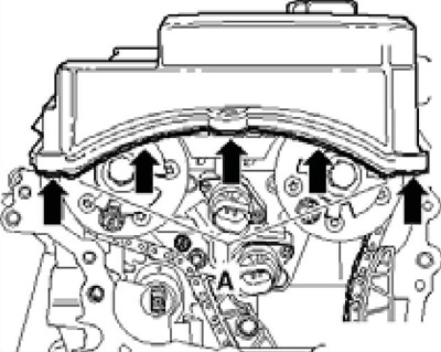
61. Slide the slightly angled top timing chain cover over the timing valves. At the same time, do not allow the cylinder head cover gasket to move back. Push the lid up first (1 per resist. illustrations) under the cylinder head cover gasket, and then slide the cover over the dowel pins in the direction of the arrow (2).
11.61 Installing the upper timing chain cover
62. Again make sure that the cylinder head cover gasket is in the correct position: it should not be shifted back.
63. Tighten the upper timing chain cover bolts by hand, and then tighten them with a force of 8 Nm.
64. Tighten the three extreme bolts of the cylinder head cover (12-14 in illustration 9.6) with a force of 10 Nm.
65. Install the vacuum pump.
66. Install the remaining parts in the reverse order of their removal.