



Contents: Removal ⬇ Installation ⬇
Removal
1. Remove the upper decorative engine cover (see the relevant section in this chapter).
2. Remove the sound insulation on the high pressure fuel pump sections if installed.
Attention.
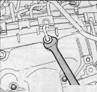
- The plugs should be disconnected from the glow plugs carefully.
- If the plug was damaged during disconnection, the entire wiring harness including the plugs would have to be replaced (plugs cannot be replaced individually). You can make your job easier by using a #12 open-end wrench.
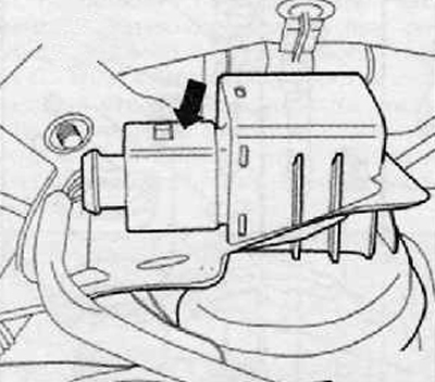
3. After disconnecting the wiring harness connector from the G581 boost pressure regulator position sensor (arrow) on the turbocharger vacuum receiver, remove the fuel line from the mount, as shown in the figure below.
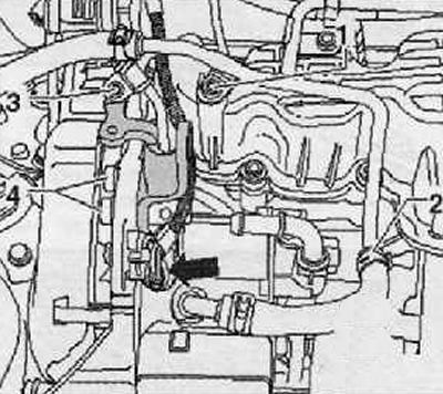
4. Unscrew the screw (3) shown in the figure below.
[Information published on the website: www.SKODABOOK.ru]
5. Remove the engine mount bracket (gray).
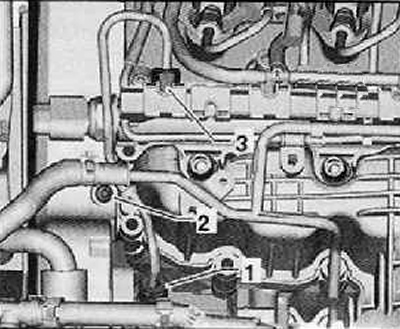
6. Remove the high pressure fuel line between the high pressure pump (1) and the fuel rail of the injection system (3), as shown in the figure below.
Note.
- The preferred sequence for loosening high pressure lines on cylinders is 4-3-2-1.
- During loosening, hold the high pressure pipe branch pipe on the pump (plunger) sections.
7. Remove the pressure line between the fuel rail and the plunger pairs.
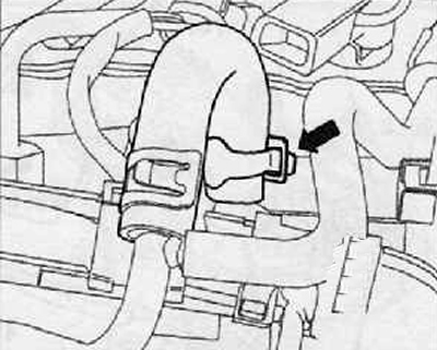
8. Loosen the elastic clamp (arrow) and disconnect the pipe from the fuel rail assembly, as shown in the figure below.
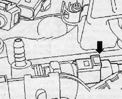
9. Disconnect the wiring harness connector at the fuel pressure regulating valve "N₂76" (arrow) as shown in the figure below.
10. After removing the cable wiring from the rail, put it aside.
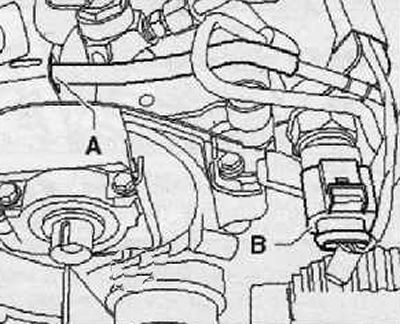
11. Disconnect the wiring harness connector at the fuel pressure sensor "G247" (B) as shown in the figure below.
12. Disconnect the vacuum line on the cylinder head cover (A) shown in the figure below.
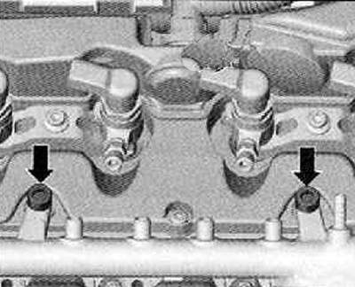
13. Unscrew the mounting screws (arrows) shown in the figure below and remove the fuel rail assembly.
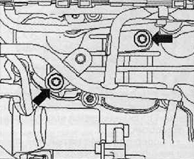
14. Unscrew the mounting screws on the intake manifold (arrows), set the return fuel line aside.
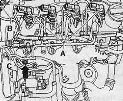
15. Disconnect the wiring harness connector from the fuel injectors (A) as shown in the figure below.
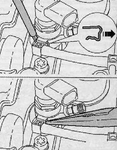
16. Unfasten the connections of the return fuel line using a screwdriver and pliers, as shown in the figure below.
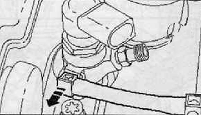
17. Disconnect the fuel return line connections from the fuel injectors by pulling them in the direction of the arrow, as shown in the figure below.
18. After removing the entire return fuel line, place it on the intake manifold.
19. Remove the remaining vacuum lines from the holder on the cylinder head cover.
20. Remove the upper part of the timing belt cover.
21. Remove the air bleed pipe between the cylinder head cover and the air intake sleeve. To do this, press the quick-release couplings.
22. Remove the fuel injectors as an assembly.
23. Unscrew the cylinder head cover mounting bolts.
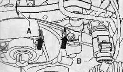
24. Remove the cylinder head cover. To do this, release the cylinder head cover from the retainers (arrows) of the rear timing belt guard, as shown in the figure below.
Installation
1. Installation is carried out in the reverse order of removal.
Note: If damaged or leaking, replace the cylinder head cover gasket.
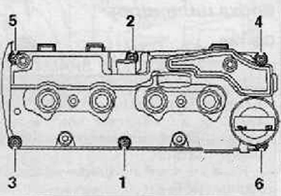
2. Tighten the cylinder head cover mounting bolts by hand in sequence (1...6).
3. The screws should be tightened in sequence (1...6) with a tightening torque of 10 Nm.
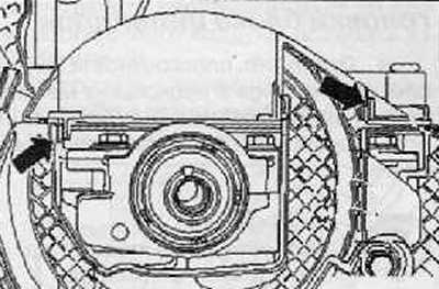
4. Ensure that the cylinder head cover is properly secured to the timing belt cover.
Note: For clarity, the camshaft drive gear is not shown in the figure below.
To do this, use a screwdriver to press on the toothed drive belt cover at the location of the clamps (arrows) against the cylinder head cover so that the clamps click into each other.
5. Check the free play between the hub and the toothed drive belt cover
6. Install the fuel injectors (for more details, see the relevant section in the chapter Engine power supply and control system).