
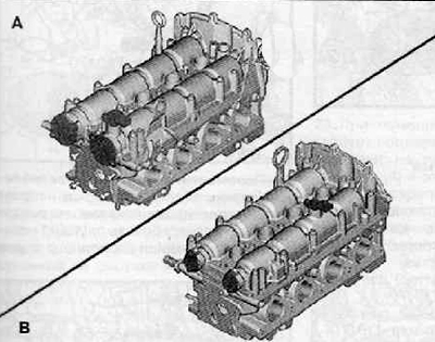
Note. There are two versions of cylinder heads shown in the figure below.
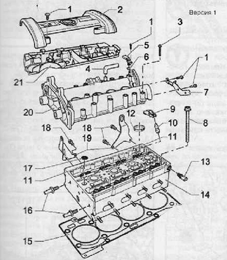
1. Mounting screw, installation torque 10 Nm
2. Cylinder head cover
3. Bolt for securing the camshaft housing, tightening torque when installing 10 Nm + tighten an additional 90° (¼ turn)
4. To the air filter
5. Camshaft position sender -G40-
6. O-ring
7. Holder
8. Cylinder head bolt
9. Rocker
10. Support element
11. Locating pins
12. O-ring
13. Oil pressure drop sensor with hydraulic drive 0.05 MPa (0.5 bar) -F1-, 25 Nm
14. Cylinder head assembly
15. Cylinder head gasket
16. Guide pins, tightening torque 20 Nm
17. Mesh oil filter
18. Fastening bolt, tightening torque for installation 20 Nm
19. Eyelets
20. Camshaft housing
21. Conduit
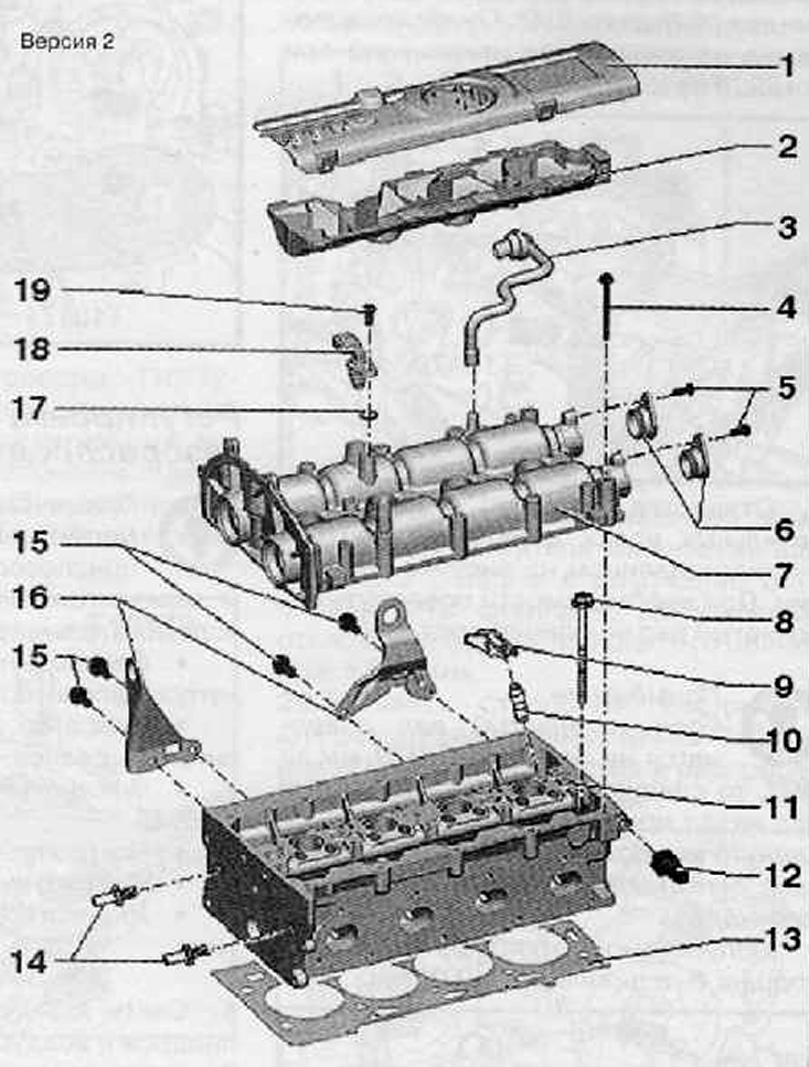
1. Cylinder head cover
2. Conduit
3. To the air filter
4. Bolt for securing the camshaft housing, tightening torque when installing 10 Nm + tighten by an angle of 90° (¼ turn)
5. Mounting bolts, tightening torque when installing 10 Nm
6. Camshaft covers
7. Camshaft housing
8. Cylinder head bolt
9. Roller rocker
10. Support element (not to be confused with hydraulic compensator)
11. Cylinder head assembly
12. Oil pressure drop sensor with hydraulic drive 0.05 MPa (0.5 bar) -F1-, 25 Nm
13. Cylinder head gasket
14. Guide bolt, installation torque 20 Nm
15. Mounting bolts, tightening torque when installing 20 Nm
16. eyelet
17. O-ring
18. Camshaft position sensor
19. Mounting bolt, tightening torque when installing 10 Nm