
Removing
1. Remove the air filter assembly.
2. Disconnect the vacuum valve (PCV valve) forced crankcase ventilation systems.
3. Remove coolant expansion tank Coolant hoses remain connected.
4. Remove the lower protective casing of the engine compartment.
5. Remove the fender liner of the right front wheel arch (for more details, see the relevant section in chapter Body).
6. Remove the V-ribbed implement drive belt (for details, see the relevant section in this chapter).
For vehicles with air conditioning
7. Unscrew the mounting bolts and remove the air conditioning compressor from the mounting bracket without disconnecting the system pipes from it.
8. Remove the holder of the tensioner and the guide roller of the ribbed belt drive attachments.
For vehicles without air conditioning
9. Remove the tensioner of the poly-V-belt of the attachment drive.
Continuation for all cars
10. Remove alternator (for more details, see the relevant section in the chapter Engine electrical equipment).
11. Unscrew the mounting bolts and remove the pulley of the liquid cooling system pump.
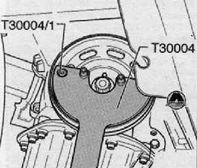
12. Unscrew the mounting bolt and remove the crankshaft pulley
Note. Hold pulley with counterhold -T30004 with journals -T30004/1- as shown in figure below.
13. Remove the mounting bolts and remove the oil pan.
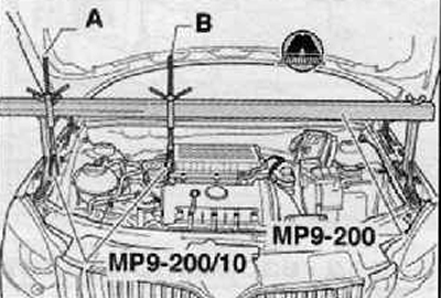
14. Install fixing suspension device -MP9-200 (10-222A) - as shown in the figure below.
Note. The picture below shows the vehicle schematically and may differ from yours.
15. The motor should be slightly raised with the lead screw (IN), lead screw (A) - remains freely suspended.
On vehicles with assembly support version 1
16. Unscrew the fastening screws (arrows), remove the engine mount as shown in the figure below.

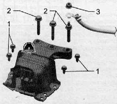
On vehicles with assembly support version 2
17. Unscrew the fastening nut (3), disconnect the wire from the engine support «masses», shown in the figure below.
18. Unscrew the fastening screws (2) And (1), remove the engine mount as shown in the figure below.
For all vehicles
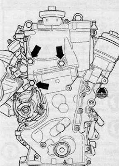
19. Unscrew the fastening bolts with an internal hexagon of the timing chain drive housing and the screws marked (arrows), as shown in the figure below.
20. Remove the timing chain cover.
Note. Ensure that the bearing bush remains in the O-ring of the timing chain housing.
21. Remove the timing chain case seal.
Installation
Attention. Protective gloves and goggles should be used when handling the seal remover and degreaser.
1. Clean sealing surfaces from seal residues (sealant) with a chemical seal remover
2. Degrease the sealing surfaces.
Note.
- Make sure that the contact surfaces on the pulley, the fixing screw, the bearing sleeve. on the double chain sprocket and the front crankshaft journal have not been contaminated with oil or grease.
- Make sure that the camshaft housing is not skewed or jammed.
3. Fit a new timing chain case gasket onto the dowel pins.
4. For ease of installation, two guide pins - M6 x 80 - should be screwed into the cylinder head and into the cylinder block.
5. Push the timing chain cover with the bearing sleeve onto the guide pins, the centering pins and the front crankshaft journal at the same time.
6. Tighten the fastening screws of the timing chain housing crosswise.
- Tightening torque for screws M6: 10 Nm.
- Tightening torque for screws M10: 50 Nm
7. Further installation is carried out in the reverse order of removal.