



Auxiliary equipment mounted on the cylinder head
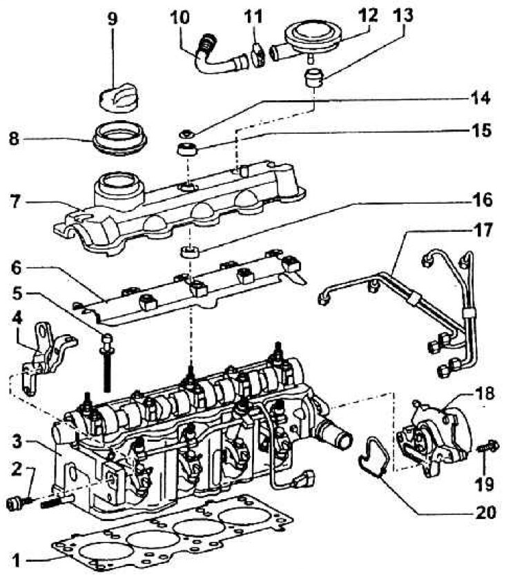
1 – cylinder head seal; 2 – bolt for fastening the slinging eyelet; 3 – assembled cylinder head installed: 4 – engine slinging eyelet; 5 – cylinder head bolts; 6 – oil splash protection cover; 7 – cylinder head cover; 8 – sealing cuff; 9 – oil filler cap; 10 – deaeration tube; 11 – clamp; 12 – pressure regulating valve; 13 – seal; 14 – shaped nut; 15 – upper sealing washer; 16 – lower part of the seal; 17 – nozzle tube; 18 – vacuum pump for creating vacuum for the brake booster; 19 – pump mounting bolt; 20 – pump seal
Assembly of valves and camshaft in the cylinder head
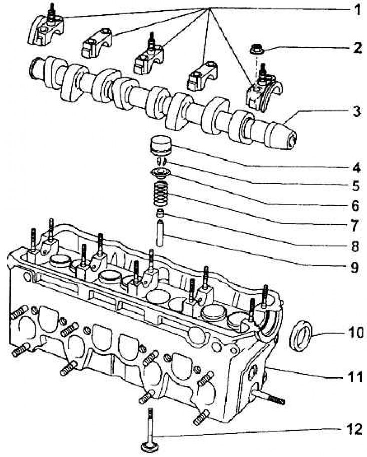
1 – camshaft bearing cover; 2 – nuts for fastening bearing caps to screwed-in bolts (M = 20 Nm); 3 – cam shaft; 4 – hydraulic pusher; 5 – valve crackers; 6 – valve plate; 7 – valve spring; 8 – sealing the valve stem with a guforo washer; 9 – valve guide; 10 – camshaft sealing washer; 11 – cylinder head; 12 – valve
Turbocharger operation diagram (turbine drive that increases the pressure of sucked air by exhaust gases)
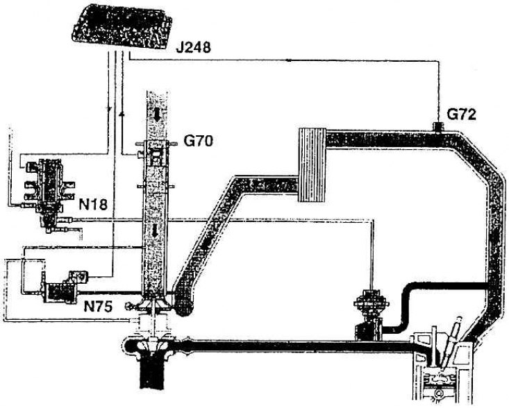
J248 – control unit; G72 – suction line temperature sensor; G70 – air intake quantity sensor; N18 – electromagnetic exhaust gas return valve; N75 – boost pressure limiting solenoid valve
Intake manifold, exhaust manifold, turbocharger and accessories
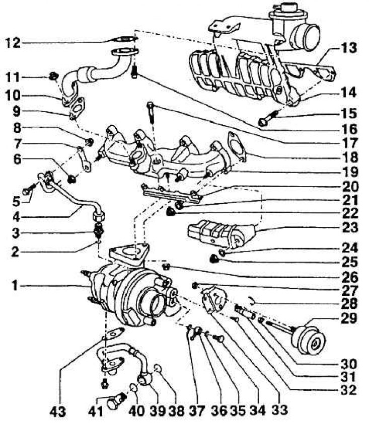
1 – turbocharger; 2 – sealing ring; 3 – threaded nipple; 4 – oil supply line; 5 – bolt; 6 – nut; 7 – pipeline bracket; 8 – nut; 9 – seal; 10 – exhaust gas return line; 11 – nut (M = 20 Nm); 12 – seal; 13 – suction pipe seal; 14 – suction pipe; 15 – suction pipe mounting bolt (M = 20 Nm); 16 – bolt for fastening the exhaust gas suction line; 17 – turbocharger mounting bolt (M = 30 Nm); 18 – sealing of the exhaust pipe channel; 19 – exhaust manifold; 20 – bracket; 21 – gasket; 22 – nut (M = 25 Nm); 23 – sheet shielding diaphragm; 24 – gasket; 25 – nut (M = 25 Nm); 26 – nut (M = 25 Nm); 27 – nut (M = 10 Nm); 28 – retaining ring; 29 – high pressure vessel; 30 – nut (M = 10Nm); 31 – control element; 32 – bracket bolt; 33 – bracket; 34 – flow bolt (M = 15 Nm); 35 – sealing washer; 36 – input eye; 37 – sealing washer; 38 – sealing washer; 39 – return oil line; 40 – sealing washer; 41 – flow bolt (M = 15 Nm); 43 – flange seal
Connection diagram for the suction air adjustment
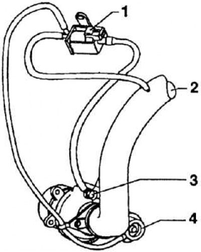
1 – electromagnetic valve for limiting boost pressure; 2 – air supply tube from the air filter; 3 – turbocharger with boost control supply; 4 – high pressure vessel for boost control valve
Cold Air Intake Parts and Radiator
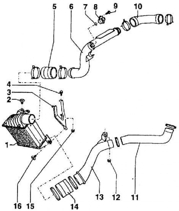
1 – sucked air radiator; 2 – radiator mounting bolt; 3 – radiator bracket; 4 – bolt; 5 – hose connection; 6 – air supply tube; 7 – washer 8 – sucked air temperature sensor; 9 – sensor mounting bolt (M = 5 Nm); 10 – air supply hose; 11 – radiator air bleed hose; 12 – bolt; 13 – air duct; 14 – hose connection; 15 – nut; 16 – bracket mounting bolt
The cylinder head, made of aluminum alloy, has eight channels: four intake and four exhaust. They are directed to the same side (rear in the direction of travel if the engine is on the car). On the back, front side, there are holes for the fuel injectors and glow plugs (see Fig. Auxiliary equipment mounted on the cylinder head).
The valve guides and seats are pressed into the head casting, both made of a special alloy. The valve guides can be replaced, but the seats cannot. Automatic limitation of the working clearance of the valves is provided by hydraulic tappets.
The cylinder head parts are the camshaft bearing caps. These caps are each seated on two screwed-in bolts and tightened with nuts. The outer and middle caps have a boss with a bolt on the upper surface for fastening the head cover. There are no bushings in the camshaft bearings (see fig. Assembly of valves and camshaft in cylinder head).
The 1.9 TDI–66 kW engine has a valve timing mechanism with an OHC, or with a camshaft in the cylinder head. Therefore, the camshaft is included in the assembly kit of the cylinder head assembly.
The cylinder head assembly is secured to the engine block with ten special bolts. The order of tightening them is shown in Fig. The order of tightening the bolts on the cylinder head; when unscrewing, proceed in the reverse order, i.e. from bolt number 10.
Maximum non-flatness of the cylinder head seating surface (warping) should not exceed 0.1 mm. When re-assembling the head, it is always necessary to change the seal and head bolts. Head assembly has its own characteristics known to all Skoda service departments. By the way, tightening the head bolts is carried out in four stages. First, the bolts (always in the order shown in Fig. Cylinder head bolt tightening order) tightened with a torque wrench to M = 35 Nm, at the next stage tightened again with a torque wrench to M = 60 Nm, at the third tightening all the bolts are turned by 90° and at the fourth – by another 90°. This is the final tightening.
For the 1.9 TDI–66 kW engine, the compression pressure is very important. It is measured at an oil temperature of at least 30°, after all glow plugs have been unscrewed. First, the fuel valve connectors and the connectors for the fuel quantity control device on the fuel pump are disconnected. Then a barograph with a screw-on adapter is installed on one of the cylinders. The pressure is measured while turning the engine with the starter.
Compression pressure - excess pressure

The camshaft timing gear is driven from the crankshaft by a toothed belt drive. It also simultaneously drives the coolant pump and the fuel pump. Their relative positions can be seen in Fig. Timing gear and coolant pump belt drive.
Valve timing (with piston stroke of 1 mm and piston clearance of 0 mm)

On the left end (if the engine is installed on the car) a vacuum pump is located on the camshaft, providing vacuum for the brake booster.
Air intake system with turbocharger and exhaust gas return system (see Fig. Turbocharger operation diagram (turbine drive that increases the pressure of sucked air by exhaust gases), fig. Intake manifold, exhaust manifold, turbocharger and accessories (detailing of individual units)).
The air supply from the air filter consists of two parts. The elastic part provides the possibility of mutual movement between the engine and the air filter, in the rigid part connected to the engine there is also a nipple for deaeration of the engine crankcase. The connection diagram of the air suction regulation is shown in Fig. The connection diagram of the sucked air regulation. The installation of the sucked air radiator and the order of its installation are shown in Fig. The details of the cold air suction and the radiator.
The aluminum casting of the suction pipe is attached to the cylinder head with bolts and sealed with a shaped seal. A mechanical deaeration valve is also part of the pipe.
The exhaust manifold is a cast iron casting with a flange for attaching the turbocharger flange, secured with three screwed-in bolts and nuts. The turbocharger, which increases the pressure of the sucked-in air with the help of a turbine, is driven by exhaust gases. The lubrication of its bearings is included in the engine lubrication system. The front part of the exhaust pipeline is connected to the turbocharger with an elastic element. The manifold is placed on the screwed-in bolts of the cylinder head and secured with nuts. Seals of individual channels are inserted between the head and the pipeline.
The air suction system is supplemented by an exhaust gas return system. The system is controlled by the control unit (J 248) via the electromagnetic exhaust gas return valve (N 18) to the mechanical valve (EGR). It has a cone-shaped valve tappet, which makes it possible to change the cross-section of the opening at different valve positions.