
Removing
1. Position #1 piston at TDC as described in Chapter 3, then remove the distributor together with the extension tube as described in Section 5.
2. Remove the generator.
3. Remove the pickup tube/strainer and remove the oil pump gears as described in Chapter 9.
4. To hold the crankshaft when the pulley bolt is loosened, engage a higher gear and have an assistant depress the brake pedal all the way. If the engine has been removed from the vehicle, block the flywheel using the method shown in Figure 12.10A.
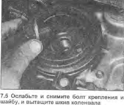
5. Loosen and remove the pulley bolt and washer (see illustration), then separate the pulley from the crankshaft.
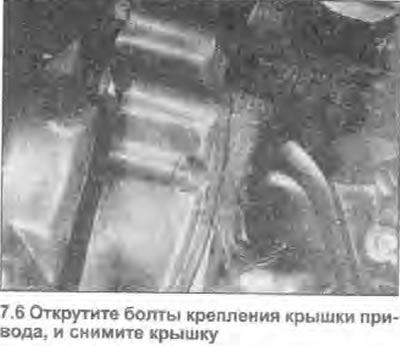
6. Loosen and remove all bolts and screws securing the drive chain cover (see illustration). Pull the cover down from the engine. Remove the gasket - it must be replaced.
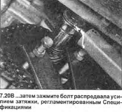
7. Using a flathead screwdriver, pry off the tab of the camshaft bolt lock washer. To prevent rotation of the camshaft when the bolt is loosened, engage a higher gear and have an assistant depress the brake pedal all the way. Alternatively, the sprocket can be blocked with a tool made from two strips of steel (one is long, the other is short) and three bolts with nuts. One bolt and nut form the pivot, and the remaining two are screwed into the ends of the yoke and inserted into the slots in the sprocket, as shown in illustration 7.20B.
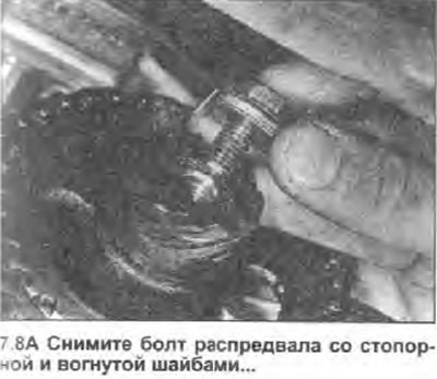
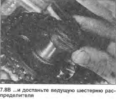
8. Turn off a bolt of a cam-shaft and remove it together with lock and concave washers. The lock washer must be discarded; it must be replaced. Remove the distributor drive gear from the end of the camshaft, noting its correct location (see illustrations).
 |  |
9. Before removing the drive chain and sprockets, note the position of the alignment marks on the sprockets and slots for the segment key in the crankshaft and camshaft (see fig. 2A.4).
10. At the same time, remove the drive chain and sprockets from the crankshaft and camshaft.
11. Remove the segment key from the slot in the crankshaft, noting its location. If the segment key in the camshaft is loose, remove it as well.
12. With the keys removed, remove the spacer, guide spacer and outer thrust washer from the end of the crankshaft, noting the location of the spacer and thrust washers.
Inspection
13. Inspect the teeth on both camshaft and crankshaft sprockets for damage and signs of wear. If there is wear or damage on any sprocket, both sprockets and chain should be replaced as a matched set.
14. Inspect the drive chain links for signs of wear on the rollers. The degree of chain wear can be assessed. by looking at how much you can bend the chain in the transverse direction. If there is excessive side play, the chain must be replaced. Please note that as a precaution, it is recommended to replace the chain, regardless of its condition, every 45,000 km, or after an engine overhaul. Although not strictly necessary, it is always worth replacing the chain and sprockets as a matched set.
15. Inspect other components for damage and signs of wear and replace as needed.
Installation
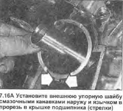
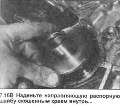
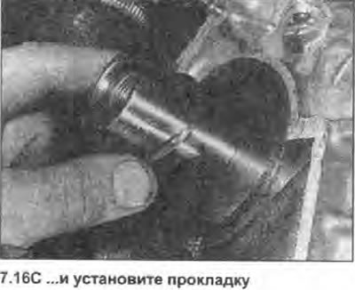
16. Install the outer thrust washer on the end of the crankshaft with its oil grooves facing out, then align the locking tab of the washer with the notch in the bottom of the cover, and install the washer in operating position. Place a guide washer on the thrust washer with the beveled edge inward and finally install the gasket (see illustrations).
 |  |
 |
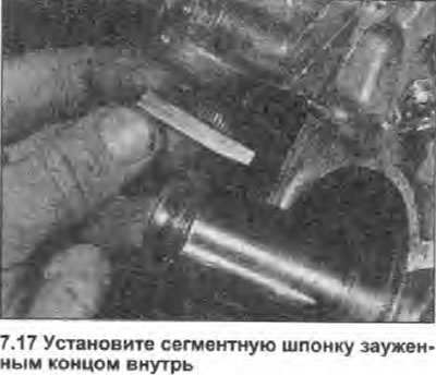
17. Install the keyway into the slot in the crankshaft with the tapered end inward (see illustration). Also install the keyway in the slot in the camshaft if it has been removed.
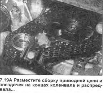
18. Guided by Fig. 2A.4, install the drive chain on the camshaft and crankshaft sprockets. The dot on the camshaft sprocket should align with the twelfth roller of the main drive chain, counting from the roller that is aligned with the dot on the crankshaft sprocket.
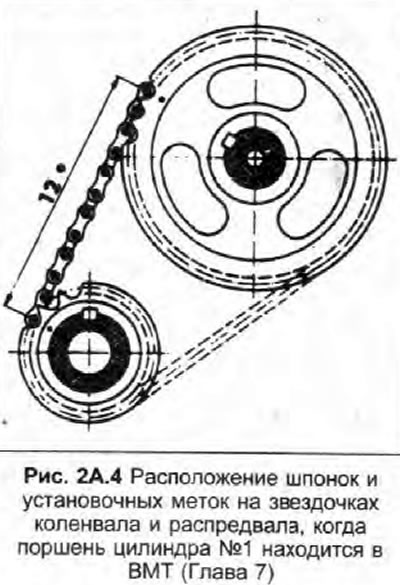
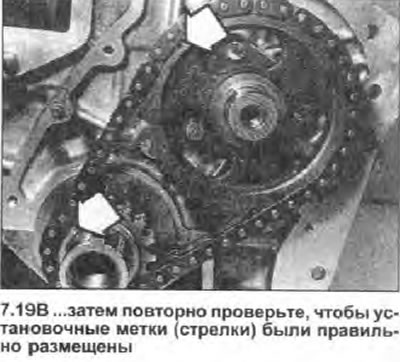
19. Make sure the segment keys in the crankshaft and camshaft are positioned as shown in Fig. 2A.4. Reinstall the chain and sprocket assembly, making sure that the alignment marks on the sprocket are facing out. Finally, recheck the position of the points (see illustrations).
 |  |
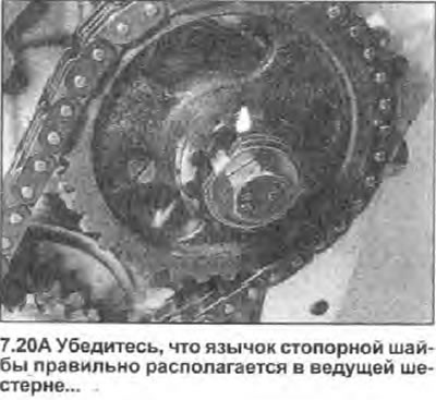
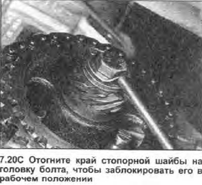
20. Place the distributor drive gear on the end of the camshaft, keeping in mind that its flange must face inward, then install the concave washer with its concave side facing outward. Install a new lock washer by aligning it with the slot in the pinion gear and install the camshaft bolt. Tighten the bolt with a torque specified specifications. Secure the bolt by bending up the edge of the lock washer (see illustrations).
 |  |
 |
21. Remove any remaining oil and gasket from the contact surfaces of the drive chain cover and block. Inspect the crankshaft oil seal in the cover for damage or contamination, and replace it if necessary as described in Chapter 11.
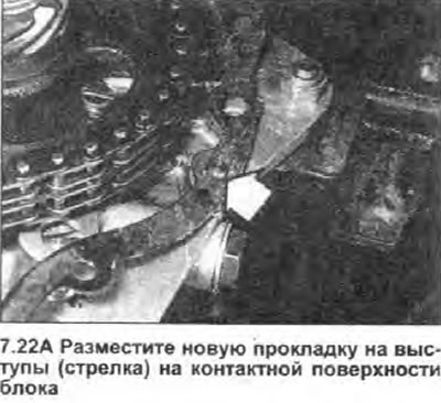
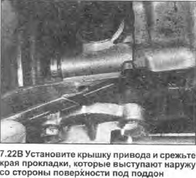
22. Install a new gasket in place in the cylinder block, securing it in position with a small amount of grease. Carefully place the drive chain cover into position. Insert the bolts and screws securing the cover, and (where possible) clamp them with a tightening force regulated specifications. Using a sharp knife, carefully cut off the edges of the gasket protruding from the side of the surface under the pallet (see illustrations).
 |  |
23. Align the groove of the crankshaft pulley with the segment key, and carefully install the pulley on the crankshaft, being careful not to damage the sealing lip of the stuffing box. Install the mounting bolt with washer, and tighten it by hand.
24. Ensure that the locking tabs of the inner and outer thrust washers are inserted into the slots on the right main bearing cap and that the thrust washers are correctly positioned. Tighten the crankshaft pulley bolt with a torque specified specifications. Note that if the thrust washers are not placed properly, the crankshaft will lock when the bolt is tightened and the thrust washers will be damaged. Make sure the crankshaft rotates freely before continuing (see illustrations).
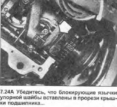 | 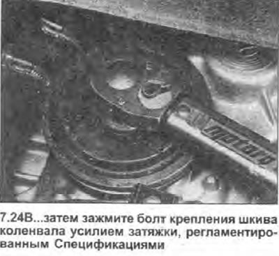 |
25. Install the gears and downpipe/oil pump strainer, then install the sump as described in Chapter 10.
26. Install the generator as described in Section 12.
27. Install the distributor as described in Section 5.