
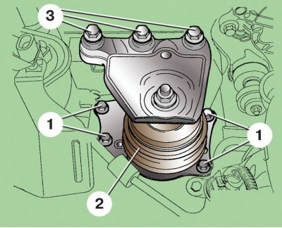
Camshaft pulley
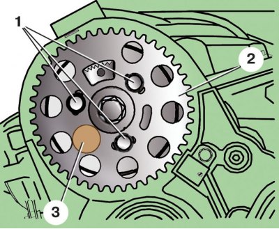
1 - pulley mounting bolts; 2 - pulley; 3 - camshaft stopper
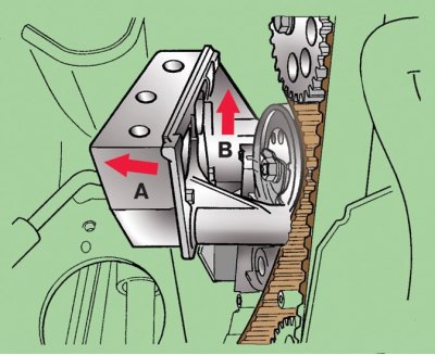
Camshaft drive belt tension
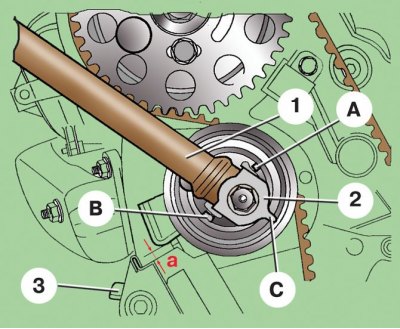
1 key; 2 - tension roller eccentric; 3 - locking plate; A, B - stops; C - protrusion of the eccentric; a - gap
Rear support of the power unit
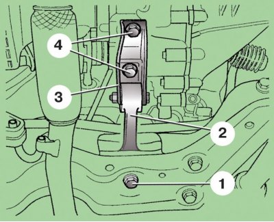
1 – a bolt of fastening of a support to a body; 2 - support; 3 - support bracket; 4 – a bolt of fastening of a support to a transmission
1. Remove the alternator drive belt (see subsection 2.3).
2. Remove the right front fender latch.
3. Remove bolts 21 (see Camshaft Drive Parts), holding the crankshaft from turning, and remove the pulley 20.
4. Turn away bolts of fastening and remove lower 19 and average 22 covers of a belt of a drive of a camshaft.
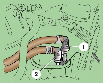
5. Remove the clamps and disconnect fuel hoses 1 and 2 from the fuel filter. Be careful - the fuel may be under pressure.
6. Remove the expansion tank without disconnecting the hoses from it, and set it aside.
7. Hook the engine with a hoist and tighten its cables to relieve the engine mounts.
8. Turn away bolts 1 and 3 fastenings of the right support of the power unit to a body and the engine (2 - support).
9. Turn away bolts 4 fastenings of a back support of the power unit to a transmission (see Powertrain Rear Support).
10. Release the latches and remove the top cover 1 (see Camshaft Drive Parts) camshaft drive belt.
11. Lower the engine by about 35 mm and unscrew the lower bracket mounting bolt 24.
12. Raise the engine about 45 mm from the normal position and unscrew the two upper bolts of the bracket 24. Remove the bracket, to do this, first turn it in the direction of arrow A, and then lift it up.
13. Lower the engine to the normal position and set the piston of the first cylinder to TDC (see subsection 2.2.2). After this, the crankshaft and camshaft must not be rotated. At service stations, the MP 1-301 tool is used to lock the camshaft, and T 10050 for the crankshaft.
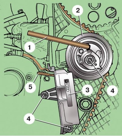
14. Insert a wrench 1 into the hex hole of the tensioner roller 2 and turn the tensioner counterclockwise so that the lock plate 5 can be inserted (3 - tension device; 4 – a bolt of fastening of the tension device).
15. Turn away bolts 4 fastenings and remove the tension device 3.
16. Remove the camshaft drive belt.
Attention! The camshaft drive belt tension can only be adjusted when the engine is cold.
17. Loosen bolts 1 (see fig. Camshaft pulley) fastening pulley 2 and turn the pulley using the oval holes clockwise until it stops.
18. With special key 1 (see fig. Camshaft drive belt tension) turn the eccentric 2 of the tension roller clockwise so that its protrusion C reaches the stop B.
19. Slide the belt over the crankshaft pulley, then over the idler pulley and camshaft pulley, and lastly over the water pump pulley.
20. Install the tensioner, tighten the bolts of its fastening.
21. Use the key 1 to turn the eccentric 2 counterclockwise (lug C turns towards stop A) so that the lock plate 3 can be removed.
22. Use the key 1 to turn the eccentric 2 clockwise (lug C turns towards stop B) until the gap a is 4±1 mm. It is convenient to check the gap size using a drill with a diameter of 4 mm as a gauge.
23. Holding the tension roller in this position, tighten its fastening nut in two stages: 1st - tighten with a torque of 20 Nm; 2nd - tighten by 45°.
24. Tighten bolts 1 (see fig. Camshaft Pulley) fastening the camshaft pulley with a torque of 25 Nm. Remove the crankshaft and camshaft lockers, if fitted.
25. Rotate the crankshaft two turns and set the No. 1 cylinder to TDC again.
26. Check gap a (see fig. Camshaft drive belt tension). If it differs from the specified (4±1) mm, adjust the gap again as described above. Check the installation of the piston of the first cylinder at TDC.
27. Install all removed parts in reverse order.