
Note.
- Necessary special devices, control and measuring devices, as well as auxiliary means:
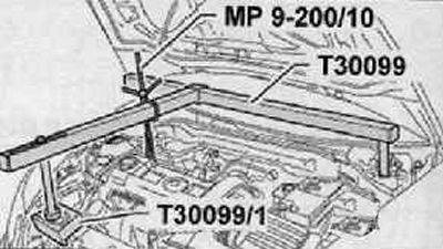
- Fixing suspension device -T30099-.
- Washer -T30099/1-.
- Counterholder -T30004 (3415) -.
- Pin -T30004/1 (3415/1) -
- Sealing agent -D 176 501 A1-.
- A means to eliminate the sealing agent Gasket Stripper (storage code GST, item No. I 34402), manufacturer Retech s.r.o
- Cleaning and degreasing agent, e.g. -0 000 401 04-.
Removing
1. Remove the top decorative engine cover.
2. Unscrew the screw shown in the figure below (1) for coolant line.
3. Pull out the hose (2) to vent the engine crankcase from the camshaft drive chain housing by pressing the circlip as shown in the figure below.
4. Disconnect the ventilation tube (1), shown in the figure below. To do this, push in the circlip.
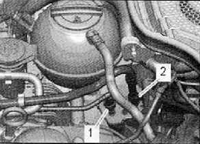
5. Disconnect the bleed hose from the activated charcoal tank (1), leading to the intake manifold as shown in the figure below.
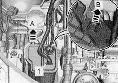
6. Unlocking the activated charcoal tank (arrow B), remove the activated charcoal tank (arrow A) up and the holder as shown in the figure below.
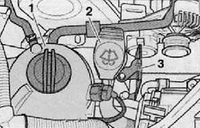
7. Detach the holder (3) activated charcoal tank shown in the figure below.
8. Unscrew the screw on the filler neck (2) washer fluid reservoir as shown in the figure below.
9. Unplug wiring harness connector for coolant shortage indicator switch -F66- at coolant expansion tank, move wiring harness free
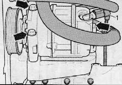
10. Unscrew the screws securing the coolant expansion tank (1), as shown in the figure below; The coolant expansion tank with hoses attached must be placed on the engine and, if necessary, tied tightly.
11. Remove the V-ribbed implement drive belt (more, see relevant section in this chapter).
12. Remove the engine cooling pump drive pulley.
13. Disconnect the wiring harness connector (1) control valve on the air conditioning compressor.
Attention.
- Risk of injury from coolant.
- The air conditioning refrigerant circuit must not be opened.
Attention.
- Risk of damage to pipes and coolant hoses.
- Coolant lines and hoses must not be twisted or bent at an acute angle.
14. Unscrew the fastening screws (arrows) air conditioner compressor as shown in the figure below.
15. Attach the A/C compressor to the complete body front wall module.
16. Remove the accessory mounting bracket.
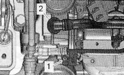
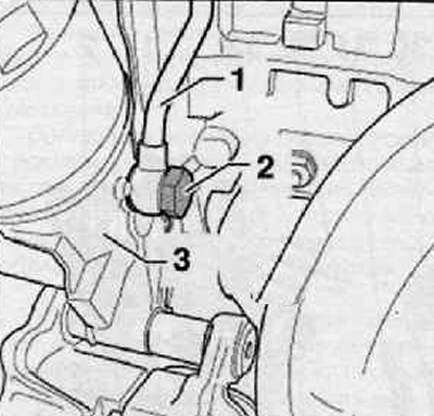
17. Unscrew the hollow screw (2) supply lubrication line (1) turbocharger from the timing chain housing (3), as shown in the figure below.
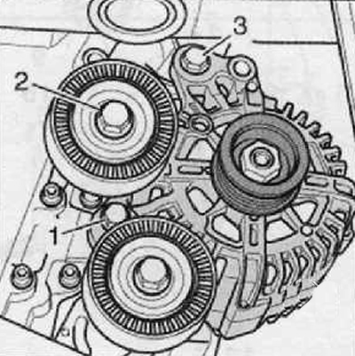
18. Remove alternator and idler pulley (2), as shown in the figure below.
19. Turn the crankshaft in the direction of movement of the engine shaft to the TDC of the 1st cylinder.
20. Remove the crankshaft pulley.
Attention.
- Risk of engine damage.
- In order to avoid slipping of the chain gear on the crankshaft from the leash, it is forbidden to turn the crankshaft when the V-ribbed belt pulley is loose.
21. Remove the oil pan.
Note. If the timing gear housing cover is removed only for the purpose of removing the cylinder head, then not the engine mount described below is used, but the engine mount described for removing the cylinder head.
22. Install the mounting bracket -T30099- as shown in the illustration and lock the engine in the assembly position.
23. The engine should be slightly preloaded.
24. Loosen the fastening nut (1) and disconnect the wire «masses», shown in the figure below. Then unscrew the fastening bolts (arrows) and remove the power unit support assembly as shown in the figure below.
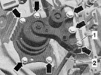
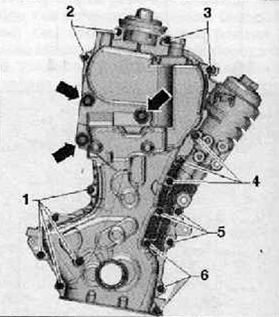
25. Unscrew the fastening screws (1...6) timing chain housing with hexagon socket and screws marked (arrows), as shown in the figure below.
26. Remove the timing chain housing assembly. To do this, raise the engine if necessary.
Note. Ensure that the crankshaft bushing remains in the timing chain housing.
27. Push the crankshaft oil seal out of the timing chain housing.
Installation
Note. Make sure that the contact surfaces on the pulley, the fixing screw, the bearing bush and on the crankshaft chain sprocket are free of oil and grease.
Attention. Protective gloves and goggles should be used when working with seal remover and degreaser.
1. Sealant residues on the sealing surfaces must be removed with a chemical sealant remover.
2. Degrease the sealing surfaces.
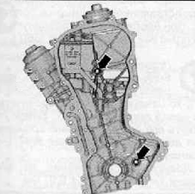
3. Install new seals (arrows) on the back side of the timing chain case, as shown in the figure below.
Note. The cover of the timing gears on the engine is sealed with a seal and also with a sealing agent D 176 501A1.
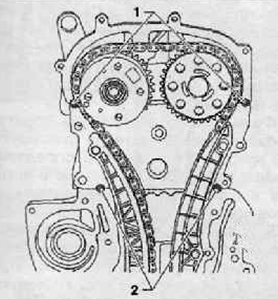
4. Sealing agent D 176 501 A1 must prevent leaks between the timing chain housing and the separation seams (1) And (2), as shown in the figure below.
- The diameter of the sealing pocket points should be 10 mm and the thickness approx. 1 mm
- The sealing agent should only be applied just before installing the timing chain housing.
5. Apply sealant (sealant) D 176 501 A1 on the separation seams between the camshaft housing and the cylinder head (1) and between the cylinder head and the cylinder block (2), as shown in the figure below.
6. Carefully push the new seal onto the dowel pins.
7. For the sake of a better installation, two M6x80 studs should be screwed into the cylinder head and into the cylinder block.
8. Install the timing chain housing together with the crankshaft main bearing bush at the same time on the studs, centering pins and on the crankshaft journal.
9. Tighten the fastening screws of the timing chain housing crosswise. Make sure the timing chain housing is not twisted during installation.
Tightening torques:
- Bolt M6 - 10 Nm.
- Bolt M10 - 50 Nm.
10. Align the motor support.
11. Install the crankshaft O-ring on the pulley side.
12. Install the pulley on the crankshaft.
13. Install the turbocharger lubrication supply line to the timing gear cover.
14. In the future, installation is carried out in the reverse order of actions than removal.
Note.
- Before proceeding with installation, lubricate all bearings and working surfaces with oil.
- If, during engine repair, metal chips or abraded material particles appear in an increased amount, this may indicate damage to the main bearings of the crankshaft or connecting rod bearings. In order to avoid subsequent damage, the following work must be carried out after repair:
- Clean the lubrication channels thoroughly.
- Replace oil spray nozzles.
- Replace oil cooler.
- Replace oil filter.