
Engine cylinder head 1.9 l, 74 kW
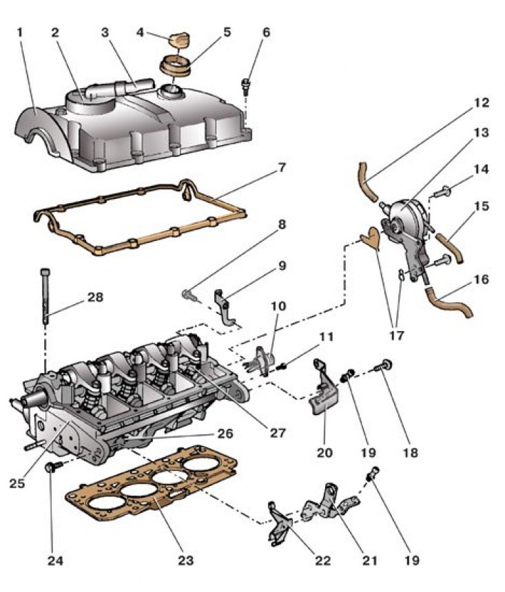
1 - block head cover; 2 - crankcase ventilation valve; 3 - crankcase ventilation hose; 4 - oil filler cap; 5 - sealing ring; 6 – a bolt of fastening of a cover; 7 - cover gasket; 8 – a bolt of fastening of an arm; 9 - bracket; 10 - connecting block of the injector harness; 11 – a bolt of fastening of a block; 12 – a vacuum hose of the amplifier of brakes; 13 - vacuum pump; 14 – a bolt of fastening of the pump; 15 - fuel supply hose; 16 - fuel drain hose; 17 - gasket; 18 - bracket bolt; 19 – a bolt with a spherical head; 20 - bracket; 21 - eye; 22 - hose holder; 23 - block head gasket; 24 – a bolt of fastening of an eye; 25 - cylinder head; 26 - glow plug; 27 - pump-injector; 28 - a bolt of fastening of a head of the block
Diesel cylinder head gasket marking
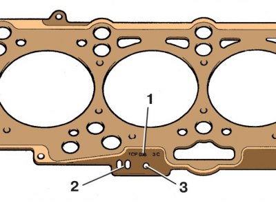
1 - part number; 2 - code; 3 - characteristic (thickness) gaskets
Heater hoses
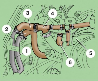
1 - heater branch pipe; 2 - a hose for draining liquid from the heater; 3 - hose for supplying fluid to the heater; 4 - tee; 5 – vacuum pump; 6 - vacuum pump hose
Turbocharger (bottom view)
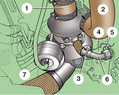
1 – a hose of a back air duct; 2 - lower air duct hose; 3 – a bolt of fastening of a turbocompressor; 4 - turbocharger bracket; 5 – a bolt of fastening of an arm; 6 - oil drain hose from the turbocharger; 7 - vacuum hose boost pressure regulator
The replacement of the gasket is shown on a diesel engine, on other engines the replacement is carried out similarly.
Attention! For diesel engines, gaskets are supplied in three standard sizes, differing in thickness, as spare parts. When replacing, you need to install a new gasket with the same markings as on the old one.
Attention! Each time the head is removed, for all engines, except for the 1.0L, 37 kW and 1.4L, 50 kW engines, the head bolts must be replaced with new ones.
Attention! For engines of 1.0 l, 37 kW and 1.4 l, 50 kW, before tightening the block head bolts, lubricate their threads with a thin layer of engine oil.
1. Disconnect the wire from the terminal «-» battery.
2. Drain the liquid from the engine cooling system (see subsection 5.13).
3. Remove the upper engine cover (see subsection 2.1).
4. Remove the air filter along with the air duct (see subsection 4.1).
5. Remove the battery and its bracket (see subsection 10.2).
6. Loosen the mounting bolts and remove the rear air duct (from air filter to turbocharger).
7. Disconnect the glow plug wire harness from the wiring harness.
8. Disconnect the muffler downpipe from the exhaust manifold (see subsection 6.2 and subsection 6.3).
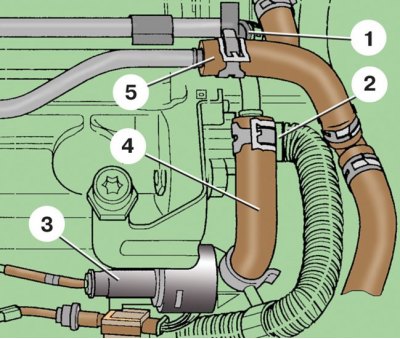
9. Disconnect hoses 1 and 2 from the turbocharger, having previously unscrewed the bolt securing the lower air duct to the bracket (see fig. Turbocharger (bottom view)).
10. Turn away a cap nut and disconnect a drain hose 6 from the block of cylinders.
11. Unscrew bolt 3, loosen bolt 5 and turn bracket 4 down.
12. Disconnect the vacuum hose 7 from the boost pressure regulator.
13. Unscrew the mounting bolts and, without disconnecting the hoses from it, remove the throttle body from the engine intake pipe. Set the throttle body aside.
14. Remove bolts 6 (see fig. Engine cylinder head 1.9 l, 74 kW) fasteners and remove the cover 1 of the head of the block and the gasket 7.
15. Disconnect hose 16 from the fuel filter and plug it so that no fuel flows out of it.
16. Disconnect the fuel supply hoses 1 and drain 4 from the fuel pipes and the coolant supply hose 5 (2 - connecting block of the injector harness; 3 - fuel temperature sensor).
17. Disconnect the block with wires from the fuel temperature sensor 3.
18. Disconnect the block with wires from block 10 (see fig. Engine cylinder head 1.9 l, 74 kW) injector harness.
19. Disconnect and remove the oil supply pipe to the turbocharger.
20. Disconnect hoses 1, 2 and 3 of the engine cooling system (4 - coolant temperature sensor).
21. Disconnect the block with wires from the coolant temperature sensor 4.
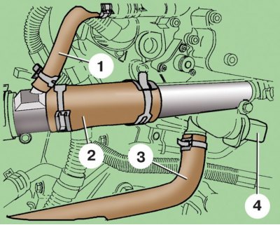
22. Disconnect hose 3 from tee 4 (see fig. heater hoses).
23. Disconnect hose 6 from pump 5.
24. Remove the camshaft drive belt (see subsection 2.4.1). Rotate the crankshaft slightly back from TDC.
25. Remove the camshaft pulley and hub (see subsection 2.8).
26. Remove the water pump (see subsection 5.5 and subsection 5.6).
27. Remove the camshaft position sensor (see subsection 4.24).
28. Remove the rear camshaft drive belt cover.
29. Screw the bolt into the power unit mounting hole so that the engine can be hung out.
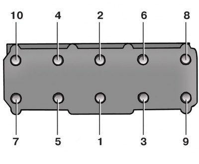
30. Turn away bolts of fastening of a head of the block of cylinders on 2-3 turns in the sequence shown in drawing, and then turn out them.
31. Remove the cylinder head. If the head cannot be torn off the block, it can be moved with gentle blows of a rubber hammer.
32. Remove the head gasket.
33. Thoroughly clean the mating surfaces of the block and head from the remnants of the old gasket, dirt and oil.
34. Remove oil from the threaded holes in the cylinder block for the head bolts.
35. Rotate the crankshaft so that all pistons are in the middle of the cylinders.
36. Install a new gasket on the guide pins 1 so that the part number on the gasket is on top. If the pins fell out, you need to insert new ones (2 - block of cylinders).
37. Install the head of the block and hand-tighten the bolts of its fastening.
38. Tighten the head mounting bolts in the sequence shown in the figure below, in four stages:
- 1st - torque 40 Nm;
- 2nd - torque 60 Nm;
- 3rd - tighten by 90°;
- 4th - tighten another 90°.
39. After installing the camshaft pulley, turn the camshaft so that the cams of the first cylinder are pointing up (from valve lifters).
40. Install all removed parts in reverse order.
The order of tightening the cylinder head bolts
Tightening torques, Nm
| Bolt of fastening of a cover of a head of the block | 10 |
| Bolt of fastening of the vacuum pump | 25 |
| glow plug | 15 |