
Note.
- Necessary special devices, control and measuring devices, as well as auxiliary means:
- Camshaft position lock -T10171 A-.
- two studs (М6х80).
- Sealing agent -D 188 003 A1-.
- A means to eliminate the sealing agent Gasket Stripper (storage code GST, item No. I 34402). manufacturer Retech s.r.o.
- Cleaning and degreasing agent, e.g. -0 000401 04-.
Removing
Note.
- This engine has the camshafts in the camshaft housing. Before removing the camshaft housing, the camshaft cover must be removed.
- The sealing surface of the camshaft housing must not be machined.
- Observe safety regulations.
Attention. Reducing the pressure in the high pressure part of the supply system.
1. Remove the top decorative engine cover assembly.
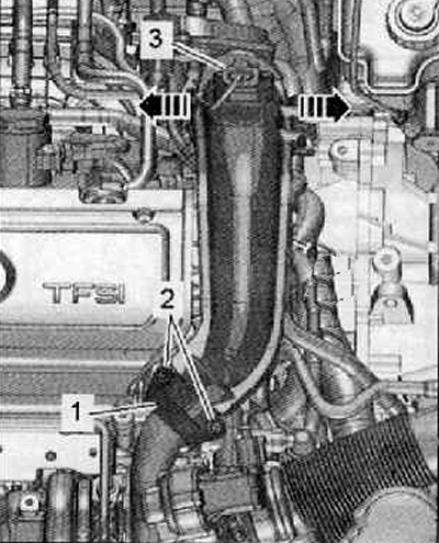
2. Unscrew the fastening screws (2), remove clamp (1), as shown in the figure below.
3. Disconnect the wiring harness connector (3) from charge pressure sender -G31- with intake air temperature sender 2 -G299-.
4. Hang the hoses on the pressure line and uncover the cabling.
5. Move clamps outward (arrows) and remove the pressure pipe upwards.
6. Then remove the pressure pipe from the turbocharger.
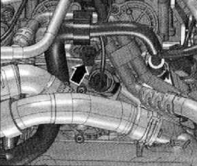
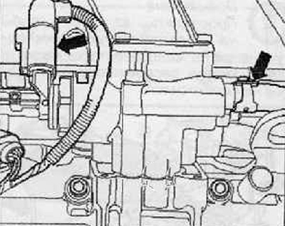
7. Disconnect the wiring harness connector (arrow) from the oil pressure drop sender -F1- as shown in the figure below.
8. Unscrew the fastening screw (1) wires «masses», which is shown in the figure below.
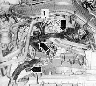
9. Unscrew the fastening screws (1) and 2 () move the pipes of the cooling system towards the left.
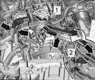
10. Unscrew the fastening screws (arrows), remove cover (1) And (2), as shown in the figure below.
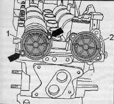
11. Remove the turbocharger assembly.
12. Remove the timing chain cover.
13. Turn the crankshaft to the TDC position of the piston of the 1st cylinder, then turn it about 45°back against the direction of rotation of the engine shaft and remove the chain sprockets together with the camshaft drive chain.
14. Disconnect the wiring harness connector from the high pressure fuel pump.
15. Remove the ignition coils.
16. To remove the holder of wires together with a plait of wires from a case of camshafts.
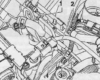
17. Disconnect the fuel supply line (right arrow) from the high pressure pump, as shown in the figure below.
18. Remove the pipeline (2), remove clamp (4) from the high pressure pipeline.
Note. When loosening the union nut, hold the threads on the high pressure pump and on the lower part of the fuel distributor with a wrench.
19. Loosen union nuts (3) And (1) on the high pressure pipe as shown in the figure below.
20. Unplug electrical harness connector at Hall sender -G40-.
21. Remove the oil level indicator.
22. Unscrew the left eye.
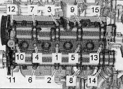
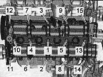
23. Unscrew the screws of the camshaft housing in the sequence (15... 1), as shown in the figure below.
24. Carefully remove the camshaft housing.
Installation
Attention.
- Before installing the camshaft housing, the studs must be screwed into the cylinder head (M6 x 80).
- The studs guide the camshaft housing, preventing the rocker arms from slipping off the hydraulic tappets.
Note. It is impossible for any of the pistons to be at TDC.
Attention. Protective gloves and goggles should be used when working with seal remover and degreaser.
1. Remove sealant residue from the cylinder head and camshaft housing with a chemical sealant remover.
2. Degrease the sealing surfaces. They must be free of oil and grease.
3. Prevent dirt and sealant residues from entering the cylinder head.
4. Turn the camshafts that actuate the intake and exhaust valves until the camshaft positioner -T10171 A- can be inserted into the holes in the camshafts as far as they will go.
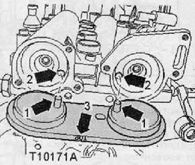
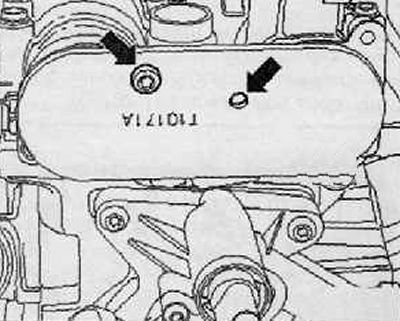
5. To lock the camshaft position lock -T10171 A-, manually screw the M6 screw into the corresponding hole (arrows), without tightening, as shown in the figure below.
Note. It should be remembered that. that the camshaft positioner -T10171 A- has different attachment points.
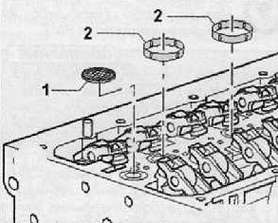
6. Replacing the mesh oil filter (1), insert it into the cylinder head as shown in the figure below.
7. Insert 4 new O-rings into the grooves of the cylinder head (2), shown in the figure below.
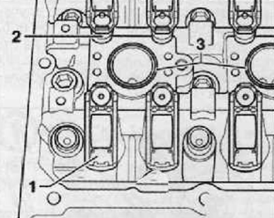
8. Make sure that all the rocker arms fit correctly on the ends of the valve stems (1) and that they are properly secured to their respective hydraulic expansion joints (2), as shown in the figure below.
9. Apply sealant (sealant) evenly and in a thin layer on the clean sealing surface of the camshaft housing.
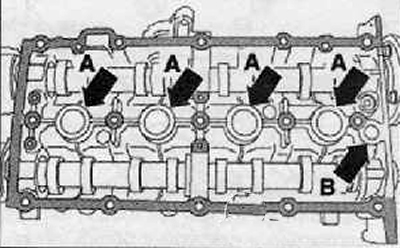
10. In the places of arrows A, no sealant is applied. O-rings inserted into the cylinder head are sealed here.
Note.
- Do not apply sealant at arrow point B. Here the mesh oil filter seals.
- The sealing agent must not be applied in an excessively thick layer, otherwise sealant residues may enter the oil channels of the lubrication system, which can lead to failure of the entire engine.
11. Before proceeding with the installation of the camshaft housing, two studs should be screwed into the cylinder head (М6х80).
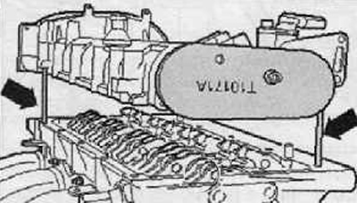
12. Carefully put the camshaft housing on the studs vertically from above (arrows) and on the dowel pins in the cylinder head as shown in the figure below.
Note. Make sure that oil residues do not drip onto the flange seal and that the camshaft housing is not distorted.
13. New camshaft housing screws must be tightened in sequence (1...15) in two approaches:
- First approach: tighten with a tightening torque of 10 Nm.
- Second approach: tighten all bolts by 90° (¼ turn).
14. Make sure that the camshaft housing is not jammed.
Note. After installing the camshaft housing, the sealing agent must dry for at least 30 minutes.
15. Adjust the valve timing in time.
16. In the future, installation is carried out in the reverse order of actions than removal. In doing so, the following instructions must be observed:
Install the timing gear cover.
Build a turbocharger
Install the pulley on the crankshaft.
Connect fuel lines.