



Note:
- Necessary special devices, control measuring devices, and auxiliary means
- Adapter for dial indicator "T10170" or "T10170 A".
- Camshaft position lock "T10171 A".
- Clamping device "T10172".
- Locking screw "T10340".
- Counter support -T30004 (3415)-
- Fixing pin "T40011".
- Dial type deviation indicator, standard.
1. Remove the upper decorative engine cover.
2. Unscrew the fastening screws (2), remove the clamp (1), as shown in the figure below.
3. Disconnect the wiring harness connector (3) from the boost pressure sensor "G31" with the intake air temperature sensor 2 "G299" as shown in the figure below.
4. Disconnect the hoses on the pressure pipeline and open the cable wiring.
5. Move the clamps outward (arrows) and pull the pressure pipe upward as shown in the figure below.
6. Then remove the turbocharger pressure line.
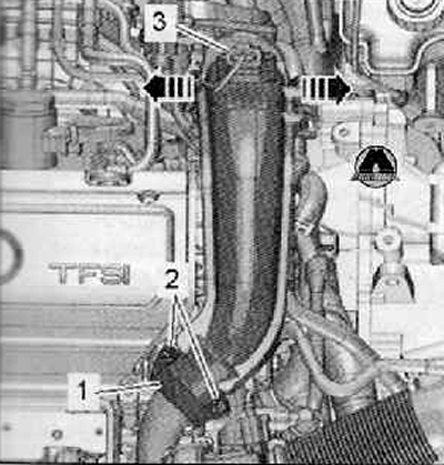
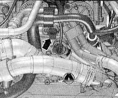
7. Disconnect the wiring harness connector (arrow) from the oil pressure drop switch-sensor "F1" as shown in the figure below.
8. Unscrew the screw (1) securing the ground wire (housing), shown in the figure below.
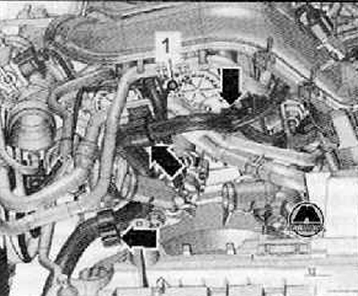
9. Unscrew the fastening screws (1) and (2), move the coolant pipes to the left to the left side of the engine compartment, as shown in the figure below.
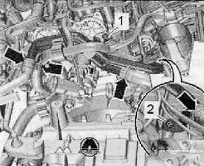
10. Unscrew the fastening screws (arrows), remove the cover (1) and (2), shown in the figure below.
11. Remove the timing chain cover.
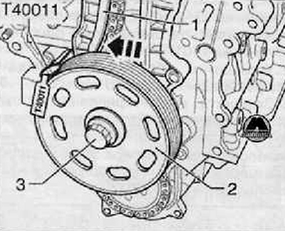
12. To be able to turn the crankshaft, install the bearing sleeve, crankshaft pulley (2) and fastening screw (3), which must be tightened to the required tightening torque (use the "T30004" controller).
13. Remove the ignition coil of the 1st cylinder.
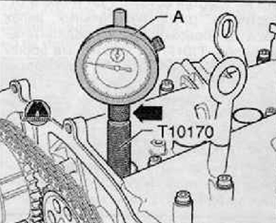
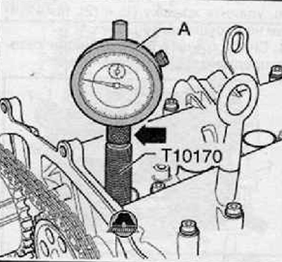
14. Screw the adapter for the dial indicator "T10170" into the spark plug thread until it stops.
15. After inserting the dial indicator (A) with the extension "T10170/1" as far as it will go, clamp it with the clamping nut (arrow), as shown in the figure below.
16. Turn the crankshaft in the direction of engine shaft travel until the piston of the 1st cylinder is at TDC.
17. Mark the position of the small dial indicator handle.
18. Turn the crankshaft 45° against the direction of the engine shaft.
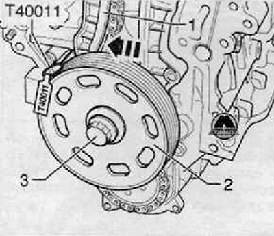
19. Move the tension bar (1) in the direction of the arrow, as shown in the figure below, fix the piston using the locking mandrel "T40011".
20. Using a suitable felt-tip pen, mark the direction of movement of the camshaft drive chain (3).
Note: The mounting screw of the mechanical device for adjusting the camshaft "2" has a left-hand thread.
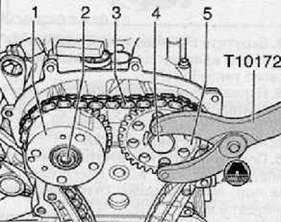
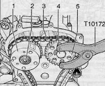
21. Unscrew the screws (2) and (4), remove the camshaft phase shifter (1) with the camshaft drive chain (3), as shown in the figure below. To support it, use the clamping device "T10172".
22. Reinstall the camshaft phase shifter (1).
23. Replace the fastening screws (2) and (4). Tighten screw (2) with a tightening torque of 40 Nm and screw (4) with a torque of 50 Nm; in this case, you should use the clamping device "T10172".
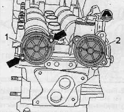
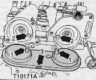
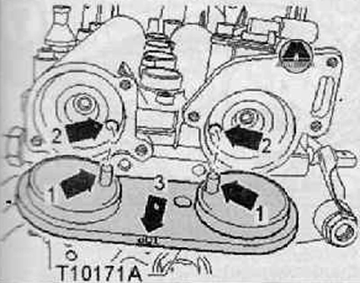
24. Turn the camshafts that operate the inlet and outlet valves until the camshaft position lock "T10171 A" can be inserted into the holes in the camshafts as far as it will go. The locking mandrels (arrows 1) must fit into the holes (arrows 2). The inscription "TOP" (arrow 3) must be legible from above.
Note: The camshafts must not be displaced during axial rotation.
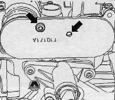
25. To lock the camshaft position lock "T10171 A", screw the M6 screw into the corresponding hole (arrows) by hand without tightening.
Note: Please note that the camshaft position lock "T10171 A" has different mounting points.
26. Loosen the screws of the chain drive sprockets on the camshafts. To do this, use the clamping device "T10172".
Caution: The camshaft locking tool "T10171 A" must not be used as a holding tool.
27. Remove the camshaft chain sprocket.
28. Place the camshaft drive chain on the camshaft chain drive sprockets (while maintaining the direction of movement of the chain) and reinstall the removed chain sprocket.
29. Screw in the camshaft screws until the chain sprockets on the camshafts can still be turned.
30. Tighten the camshaft drive chain by pulling out the locking mandrel "T40011".
31. Turn the crankshaft in the direction of the engine shaft stroke until the piston of the 1st cylinder is at TDC. Permissible deviation from TDC of the piston of the 1st cylinder: ±0.01 mm.
Note: If the crankshaft rotates more than 0.01 mm past TDC, turn the crankshaft back approximately 45°. Then turn it in the direction of engine shaft rotation to the TDC position of the 1st cylinder.
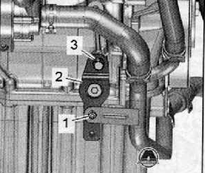
32. Unscrew the fastening screws (1) (8 Nm) and (3) (40 Nm), move the holder (2) of the coolant pipe to the right, as shown in the figure below.
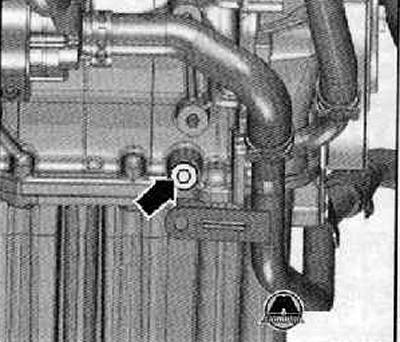
33. Unscrew the threaded plug (arrow) of the TDC hole on the cylinder block.
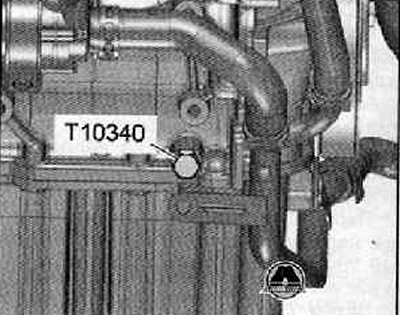
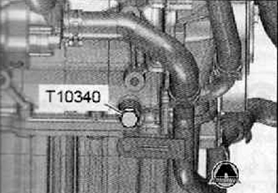
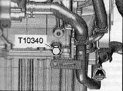
34. Screw the locking screw "T10340" into the cylinder block until it stops, tighten it with a torque of 30 Nm.
Note: The crankshaft is locked with the "T10340" locking screw only in the direction of rotation of the engine shaft.
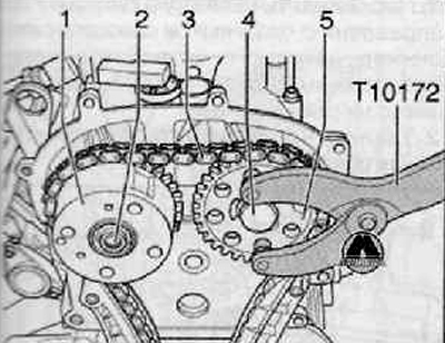
35. Using the clamping device "T10172", hold the camshaft chain sprockets (1) and (5) in this position and tighten the screw (2) (left hand thread) with a torque of 40 Nm and screw (4) with a torque of 50 Nm.
Note: When tightening the camshaft bolts, the crankshaft must not be allowed to turn, and the camshaft drive chain "3" must remain taut on both sides.
36. Remove the stopper "T10171 A" shown in the figure below.
37. Unscrew the locking screw "T10340" from the cylinder block.
38. Turn the crankshaft 2 revolutions in the direction of engine shaft rotation to the TDC position of the 1st cylinder. Permissible deviation from the TDC of the piston of the 1st cylinder: ±0.01 mm.
39. The camshaft position lock "T10171 A" should be inserted into the camshaft holes until it stops.
If it is not possible to insert the camshaft position lock "T10171 A"
40. Repeat the adjustment.
If it is possible to insert the camshaft position lock "T10171 A"
41. Screw the fixing screw "T10340" into the cylinder block until it stops.
42. Tighten the fixing screw "T10340" with a tightening torque of 30 Nm.
43. Remove the camshaft position lock "T10171 A", hold the camshaft chain sprockets with the clamping device "T10172" and turn the screws (2) (left hand thread) and (4) with a rigid wrench an additional 90° (¼ turn).
Note.
- The camshaft phase shifter mounting screw (2) has a left-hand thread.
- The camshaft timing chain sprockets must not rotate on the camshaft during tightening.
44. The installation is then carried out in the reverse order of actions than the removal. In this case, it is necessary to observe the following instructions.
Note: The "T10340" locking screw remains in the cylinder block until the pulley is installed on the crankshaft.
45. Install the timing gear cover.
46. Install the pulley on the crankshaft.
47. Install the poly V-belt.
48. Replace the camshaft cover sealing rings and lubricate them with oil before installation.